Bridging and Switching
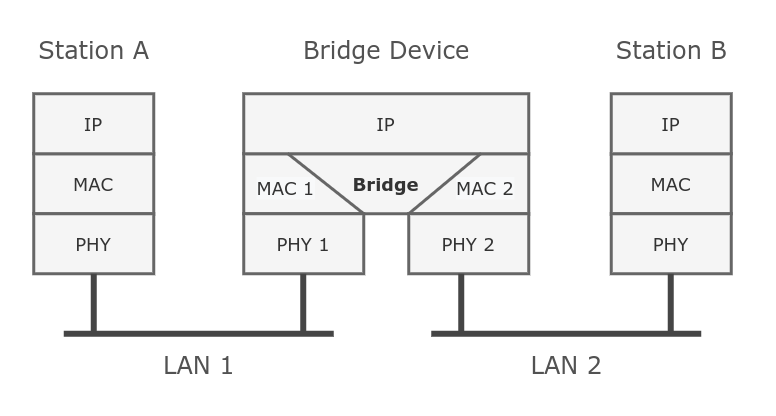
Ethernet-like networks (Ethernet, Ethernet over IP, IEEE 802.11 in ap-bridge or bridge mode, WDS, VLAN) can be connected together using MAC bridges. The bridge feature allows the interconnection of hosts connected to separate LANs (using EoIP, geographically distributed networks can be bridged as well if any kind of IP network interconnection exists between them) as if they were attached to a single LAN. As bridges are transparent, they do not appear in the traceroute list, and no utility can make a distinction between a host working in one LAN and a host working in another LAN if these LANs are bridged. However, depending on the way the LANs are interconnected, latency and data rate between hosts may vary.
Network loops may emerge (intentionally or not) in complex topologies. Without any special treatment, loops would prevent the network from functioning normally, as they would lead to avalanche-like packet multiplication. Each bridge runs an algorithm that calculates how the loop can be prevented. (R/M)STP allows bridges to communicate with each other, so they can negotiate a loop-free topology. All other alternative connections that would otherwise form loop are put on standby, so that should the main connection fail, another connection could take its place. This algorithm exchanges configuration messages (BPDUs - Bridge Protocol Data Unit) periodically, so that all bridges are updated with the newest information about changes in the network topology. (R/M)STP selects a root bridge, which is responsible for network reconfiguration, such as blocking and opening ports on other bridges. The root bridge is the bridge with the lowest bridge ID.
Bridge Interface Setup
To combine a number of networks into one bridge, a bridge interface should be created. Later, all the desired interfaces should be set up as its ports. By default, bridge MAC address will be chosen automatically, depending on the bridge port configuration. To avoid unwanted MAC address changes, it is recommended to disable auto-mac and manually specify the MAC address by using admin-mac.
Sub-menu: /interface/bridge
| Property | Description |
|---|---|
| add-dhcp-option82 (yes | no; Default: no) | Important: Starting from RouterOS version 7.23, this setting has been removed. Custom Remote ID and Circuit ID values can now be configured using predefined variables (such as BRIDGEMAC, HOSTNAME, INTERFACE, VID). See the dhcp-agent-circuit-id and dhcp-agent-remote-id properties below for details. If this setting was enabled in earlier versions (7.22 or earlier), upgrading will automatically update the configuration to the new format. Whether to add DHCP Option 82 information (Agent Remote ID and Agent Circuit ID) to DHCP packets. Can be used together with an Option 82 capable DHCP server to assign IP addresses and implement policies. This property only has an effect when dhcp-snooping is set to yes. In RouterOS versions 7.22 or earlier, the values are predefined and cannot be modified:
vlan-filtering=yes): Agent Remote ID - cc:2d:e0:01:6a:43 Agent Circuit ID - ether2:10 |
| admin-mac (MAC address; Default: none) | Static MAC address of the bridge. This property only has an effect when auto-mac is set to no. |
| ageing-time (time; Default: 00:05:00) | How long a host's information will be kept in the bridge database. |
| arp (disabled | enabled | local-proxy-arp | proxy-arp | reply-only; Default: enabled) | Address Resolution Protocol setting
|
| arp-timeout (auto | integer; Default: auto) | How long the ARP record is kept in the ARP table after no packets are received from an IP address. Value auto equals the value of arp-timeout in /ip/settings, default is 30s. |
| auto-mac (yes | no; Default: yes) | When auto-mac=yes is configured, the bridge will automatically select a MAC address for the bridge interface based on the following order of priority:
The current MAC address and its priority level are saved and will be reused after a reboot. When auto-mac=no is configured, you can set a static MAC address manually using the admin-mac property. |
| comment (string; Default: ) | Short description of the interface. |
| dhcp-agent-circuit-id (string; Default: !dhcp-agent-circuit-id) | Specify the Circuit ID suboption value of Option 82 for DHCP messages passing through the bridge. The string length is limited to 255 characters. This setting replaces the now deprecated add-dhcp-option82 property. If add-dhcp-option82 was enabled in earlier versions (7.22 or earlier), upgrading will automatically update the configuration to the new format: $(INTERFACE):$(VID). This format will also be shown when configuring the setting through the GUI. The following variables are supported:
routeros<br/>/interface/bridge<br/>add add-dhcp-option82=yes dhcp-agent-circuit-id="interface: \$(INTERFACE), vlan: \$(VID)" dhcp-snooping=yes name=bridge1 vlan-filtering=yes<br/> This property has an effect only when dhcp-snooping is set to yes. |
| dhcpv6-agent-circuit-id (string; Default: !dhcpv6-agent-circuit-id) | Specify the Interface ID suboption value of Option 18 for DHCPv6 messages passing through the bridge. The dhcpv6-agent-circuit-id property follows the same rules as dhcp-agent-circuit-id. |
| dhcp-agent-remote-id (string; Default: !dhcp-agent-remote-id) | Specify the Remote ID suboption value of Option 82 for DHCP messages passing through the bridge. The string length is limited to 255 characters. This setting replaces the now deprecated add-dhcp-option82 property. If add-dhcp-option82 was enabled in earlier versions (7.22 or earlier), upgrading will automatically update the configuration to the new format: $(BRIDGEMAC). This format will also be shown when configuring the setting through the GUI. The following variables are supported:
routeros<br/>/interface/bridge<br/>add add-dhcp-option82=yes dhcp-agent-remote-id="ip: 192.168.88.1, identity: \$(HOSTNAME), mac: \$(BRIDGEMAC)" dhcp-snooping=yes name=bridge1 vlan-filtering=yes<br/> This property has an effect only when dhcp-snooping is set to yes. |
| dhcpv6-agent-remote-id (string; Default: !dhcpv6-agent-remote-id) | Specify the Remote ID suboption value of Option 37 for DHCPv6 messages passing through the bridge. The dhcpv6-agent-remote-id property follows the same rules as dhcp-agent-remote-id. |
| dhcp-snooping (yes | no; Default: no) | Enables or disables DHCP Snooping on the bridge. Caution: Enabling the DHCP snooping feature will turn off bridge fast-path, which in turn affects the ability to fasttrack connections going over that bridge. |
| dhcpv6-snooping(yes | no; Default: no) | Enables or disables DHCPv6 Snooping on the bridge. Caution: Enabling the DHCP snooping feature will turn off bridge fast-path, which in turn affects the ability to fasttrack connections going over that bridge. |
| disabled (yes | no; Default: no) | Changes whether the bridge is disabled. |
| ether-type (0x9100 | 0x8100 | 0x88a8; Default: 0x8100) | Changes the EtherType, which will be used to determine if a packet has a VLAN tag. Packets that have a matching EtherType are considered as tagged packets. This property only has an effect when vlan-filtering is set to yes. |
| fast-forward (yes | no; Default: yes) | A special and faster case of Fast Path which works only on bridges with 2 interfaces (enabled by default only for new bridges). More details can be found in the Fast Forward section. |
| forward-delay (time; Default: 00:00:15) | The time which is spent during the initialization phase of the bridge interface (i.e., after router startup or enabling the interface) in the listening/learning state before the bridge will start functioning normally. |
| forward-reserved-addresses (yes | no: Default: no) | Whether to forward IEEE reserved multicast MAC addresses that are in the 01:80:C2:00:00:0x range. Bridges compliant with R/M/STP standards should refrain from forwarding these packets; this property can only be applied when protocol-mode is set to none. Enabling forwarding of reserved MAC addresses may affect certain protocols relying on these addresses. It is advisable to enable forwarding only when absolutely necessary, such as in transparent bridging setups (e.g., extending long links, using bridges as media converters, or conducting network analysis). Here are some notable MAC addresses and protocols used by RouterOS:
Important: The Flow Control MAC address 01:80:C2:00:00:01 is an exception; it does not get forwarded by the bridge. |
| frame-types (admit-all | admit-only-untagged-and-priority-tagged | admit-only-vlan-tagged; Default: admit-all) | Specifies allowed frame types on a bridge port. This property only has an effect when vlan-filtering is set to yes. |
| igmp-snooping (yes | no; Default: no) | Enables multicast group and port learning to prevent multicast traffic from flooding all interfaces in a bridge. |
| igmp-version (2 | 3; Default: 2) | Selects the IGMP version in which IGMP membership queries will be generated when the bridge interface is acting as an IGMP querier. This property only has an effect when igmp-snooping and multicast-querier are set to yes. |
| ingress-filtering (yes | no; Default: yes) | Enables or disables VLAN ingress filtering, which checks if the ingress port is a member of the received VLAN ID in the bridge VLAN table. By default, VLANs that don't exist in the bridge VLAN table are dropped before they are sent out (egress), but this property allows you to drop the packets when they are received (ingress). Should be used with frame-types to specify if the ingress traffic should be tagged or untagged. This property only has an effect when vlan-filtering is set to yes. The setting is enabled by default since RouterOS v7. |
| l2mtu (read-only; Default: ) | L2MTU indicates the maximum size of the frame without a MAC header that can be sent by this interface. The L2MTU value will be automatically set by the bridge and it will use the lowest L2MTU value of any associated bridge port. This value cannot be manually changed. |
| last-member-interval (time; Default: 1s) | When the last client on the bridge port unsubscribes from a multicast group and the bridge is acting as an active querier, the bridge will send a group-specific IGMP/MLD query, to make sure that no other client is still subscribed. The setting changes the response time for these queries. In case no membership reports are received in a certain time period (last-member-interval * last-member-query-count), the multicast group is removed from the multicast database (MDB). If the bridge port is configured with fast-leave, the multicast group is removed right away without sending any queries. This property only has an effect when igmp-snooping and multicast-querier are set to yes. |
| last-member-query-count (integer: 0..4294967295; Default: 2) | How many times should last-member-interval pass until the IGMP/MLD snooping bridge stops forwarding a certain multicast stream. This property only has an effect when igmp-snooping and multicast-querier are set to yes. |
| max-hops (integer: 6..40; Default: 20) | Bridge count which a BPDU can pass in an MSTP enabled network in the same region before BPDU is being ignored. This property only has an effect when protocol-mode is set to mstp. |
| max-learned-entries (integer: 0..4294967295 | auto | unlimited; Default: auto) | Sets the maximum number of learned hosts for the bridge interface. The default value is auto, and it depends on the installed amount of RAM. It is possible to set a higher value than the default or choose the unlimited option, but it increases the risk of an out-of-memory condition. The default values for certain RAM sizes:
/interface/bridge/host table nor can they be monitored. Additionally, hitting this limit could impact MLAG host synchronization. This setting has been available since RouterOS version 7.16. |
| max-message-age (time: 6s..40s; Default: 00:00:20) | Changes the Max Age value in BPDU packets, which are transmitted by the root bridge. A root bridge sends BPDUs with Max Age set to max-message-age value and a Message Age of 0. Every sequential bridge will increment the Message Age before sending its BPDUs. Once a bridge receives a BPDU where Message Age is equal to or greater than Max Age, the BPDU is ignored. This property only has an effect when protocol-mode is set to stp or rstp. |
| membership-interval (time; Default: 4m20s) | The amount of time after an entry in the Multicast Database (MDB) is removed if no IGMP/MLD membership reports are received on a bridge port. This property only has an effect when igmp-snooping is set to yes. |
| mld-version (1 | 2; Default: 1) | Selects the MLD version in which MLD membership queries will be generated, when the bridge interface is acting as an MLD querier. This property only has an effect when the bridge has an active IPv6 address, igmp-snooping and multicast-querier are set to yes. |
| mtu (integer; Default: auto) | Maximum transmission unit. By default, the bridge will set MTU automatically and it will use the lowest MTU value of any associated bridge port. The default bridge MTU value without any bridge ports added is 1500. The MTU value can be set manually, but it cannot exceed the bridge L2MTU or the lowest bridge port L2MTU. If a new bridge port is added with L2MTU which is smaller than the actual-mtu of the bridge (set by the mtu property), then the manually set value will be ignored and the bridge will act as if mtu=auto is set. When adding VLAN interfaces on the bridge, and when VLAN is using higher MTU than the default 1500, it is recommended to manually set the MTU of the bridge. |
| multicast-querier (yes | no; Default: no) | Multicast querier generates periodic IGMP/MLD general membership queries to which all IGMP/MLD capable devices respond with an IGMP/MLD membership report. Usually, a PIM (multicast) router or IGMP proxy generates these queries. By using this property you can make an IGMP/MLD snooping enabled bridge generate IGMP/MLD general membership queries. This property should be used whenever there is no active querier (PIM router or IGMP proxy) in a Layer2 network. Without a multicast querier in a Layer2 network, the Multicast Database (MDB) is not being updated; the learned entries will timeout and IGMP/MLD snooping will not function properly. Only untagged IGMP/MLD general membership queries are generated. IGMP queries are sent with IPv4 0.0.0.0 source address, MLD queries are sent with the IPv6 link-local address of the bridge interface. The bridge will not send queries if an external IGMP/MLD querier is detected (see the monitoring values igmp-querier and mld-querier). This property only has an effect when igmp-snooping is set to yes. |
| multicast-router (disabled | permanent | temporary-query; Default: temporary-query) | A multicast router port is a port where a multicast router or querier is connected. On this port, unregistered multicast streams and IGMP/MLD membership reports will be sent. This setting changes the state of the multicast router for a bridge interface itself. This property can be used to send IGMP/MLD membership reports to the bridge interface for further multicast routing or proxying. This property only has an effect when igmp-snooping is set to yes.
|
| name (text; Default: bridgeN) | Name of the bridge interface. |
| port-cost-mode (long | short; Default: long) | Changes the port path-cost and internal-path-cost mode for bridged ports, utilizing automatic values based on interface speed. This setting does not impact bridged ports with manually configured path-cost or internal-path-cost properties. Below are examples illustrating the path-costs corresponding to specific data rates (with proportionate calculations for intermediate rates): |
| Data rate | Long |
| 10 Mbps | 2,000,000 |
| 100 Mbps | 200,000 |
| 1 Gbps | 20,000 |
| 10 Gbps | 2,000 |
| 25 Gbps | 800 |
| 40 Gbps | 500 |
| 50 Gbps | 400 |
| 100 Gbps | 200 |
| priority (integer: 0..65535 decimal format or 0x0000-0xffff hex format; Default: 32768 / 0x8000) | Bridge priority, used by R/STP to determine the root bridge, used by MSTP to determine the CIST and IST regional root bridge. This property has no effect when protocol-mode is set to none. |
| protocol-mode (none | rstp | stp | mstp; Default: rstp) | Select Spanning tree protocol (STP) or Rapid spanning tree protocol (RSTP) to ensure a loop-free topology for any bridged LAN. RSTP provides a faster spanning tree convergence after a topology change. Select MSTP to ensure loop-free topology across multiple VLANs. The forwarding of reserved MAC addresses that are in the 01:80:C2:00:00:0x range is separated from protocol-mode=none, and is now available as a controllable property forward-reserved-addresses since RouterOS v7.16. |
| pvid (integer: 1..4094; Default: 1) | Port VLAN ID (pvid) specifies which VLAN the untagged ingress traffic is assigned to. It applies e.g. to frames sent from bridge IP and destined to a bridge port. This property only has an effect when vlan-filtering is set to yes. |
| querier-interval (time; Default: 4m15s) | Changes the timeout period for detected querier and multicast-router ports. This property only has an effect when igmp-snooping is set to yes. |
| query-interval (time; Default: 2m5s) | Changes the interval at which IGMP/MLD general membership queries are sent out when the bridge interface is acting as an IGMP/MLD querier. The interval takes place when the last startup query is sent. This property only has an effect when igmp-snooping and multicast-querier is set to yes. |
| query-response-interval (time; Default: 10s) | The setting changes the response time for general IGMP/MLD queries when the bridge is active as an IGMP/MLD querier. This property only has an effect when igmp-snooping and multicast-querier is set to yes. |
| region-name (text; Default: ) | MSTP region name. This property only has an effect when protocol-mode is set to mstp. |
| region-revision (integer: 0..65535; Default: 0) | MSTP configuration revision number. This property only has an effect when protocol-mode is set to mstp. |
| ra-guard (yes | no; Default: no) | RA guard - a security feature that validates incoming Router Advertisements against a list of authorized, trusted ports. |
| startup-query-count (integer: 0..4294967295; Default: 2) | Specifies how many times general IGMP/MLD queries must be sent when the bridge interface is enabled or the active querier times out. This property only has an effect when igmp-snooping and multicast-querier is set to yes. |
| startup-query-interval (time; Default: 31s250ms) | Specifies the interval between startup general IGMP/MLD queries. This property only has an effect when igmp-snooping and multicast-querier is set to yes. |
| transmit-hold-count (integer: 1..10; Default: 6) | The Transmit Hold Count used by the Port Transmit state machine to limit the transmission rate. |
| vlan-filtering (yes | no; Default: no) | Globally enables or disables VLAN functionality for the bridge. |
Changing certain properties can cause the bridge to temporarily disable all ports. This must be taken into account whenever changing such properties on production environments since it can cause all packets to be temporarily dropped. Such properties include vlan-filtering, protocol-mode, igmp-snooping, fast-forward and others.
Example
The following example demonstrates how to create and verify a basic bridge interface for simple Layer 2 switching. This configuration creates a bridge that combines multiple Ethernet ports into a single switched network segment.
[admin@MikroTik] > /interface/bridge/add
[admin@MikroTik] > print
Flags: X - disabled, R - running
0 R name="bridge1" mtu=auto actual-mtu=1500 l2mtu=65535 arp=enabled arp-timeout=auto mac-address=5E:D2:42:95:56:7F protocol-mode=rstp fast-forward=yes
igmp-snooping=no auto-mac=yes ageing-time=5m priority=0x8000 max-message-age=20s forward-delay=15s transmit-hold-count=6 vlan-filtering=no
dhcp-snooping=no
Bridge Monitoring
To monitor the current status of a bridge interface, use the monitor command.
Sub-menu: /interface/bridge/monitor
| Property | Description |
|---|---|
| bridge-id (priority.MAC address) | Local bridge identifier, which is in the form of bridge-priority.bridge-MAC-address. |
| current-mac-address (MAC address) | Current MAC address of the bridge. |
| designated-port-count (integer) | Number of designated bridge ports. |
| declared-vlan-ids (integer 1..4094) | VLANs declared on the bridge interface via MVRP protocol. |
| fast-forward (yes | no) | Whether bridge fast-forward is active. |
| igmp-querier (none | interface & IPv4 address) | Shows a bridge port and source IP address from the detected IGMP querier. Only shows detected external IGMP querier, local bridge IGMP querier (including IGMP proxy and PIM) will not be displayed. Monitoring value appears only when igmp-snooping is enabled. |
| mld-querier (none | interface & IPv6 address) | Shows a bridge port and source IPv6 address from the detected MLD querier. Only shows detected external MLD querier, local bridge MLD querier will not be displayed. Monitoring value appears only when igmp-snooping is enabled and the bridge has an active IPv6 address. |
| mst-config-digest (integer) | Computed hash of VLAN mappings to MST Instance IDs. |
| multicast-router (yes | no) | Shows if a multicast router is detected on the port. Monitoring value appears only when igmp-snooping is enabled. |
| port-count (integer) | Number of the bridge ports. |
| regional-root-bridge-id (priority.MAC address) | The regional root bridge ID, which is in the form of bridge-priority.bridge-MAC-address. Only applies when MSTP is enabled. |
| registered-vlan-ids (integer 1..4094) | VLANs registered on the bridge interface via MVRP protocol. |
| root-bridge (yes | no) | Shows whether the bridge is the root bridge of the spanning tree. |
| root-bridge-id (priority.MAC address) | The root bridge ID, which is in the form of bridge-priority.bridge-MAC-address. |
| root-path-cost (integer) | The total cost of the path to the root-bridge. |
| root-port (name) | Port to which the root bridge is connected. |
| state (enabled | disabled) | State of the bridge. |
[admin@MikroTik] /interface/bridge/monitor bridge1
state: enabled
current-mac-: 2C:C8:1B:FF:92:F4
-id: 0x1000.2C:C8:1B:FF:92:F4
root-: yes
root--id: 0x1000.2C:C8:1B:FF:92:F4
regional-root--id: 0x1000.2C:C8:1B:FF:92:F4
root-path-cost: 0
root-: none
-count: 2
designated--count: 2
mst-config-digest: d2b171a8ad95f593c241fc33d419a88c
fast-forward: no
multicast-router: no
igmp-querier: none
mld-querier: none
declared--ids: 1
registered--ids: 1
Spanning Tree Protocol
RouterOS bridge interfaces are capable of running Spanning Tree Protocol to ensure a loop-free and redundant topology. For small networks with just 2 bridges, STP does not bring many benefits, but for larger networks, properly configured STP is very crucial, leaving STP-related values at default may result in a completely unreachable network in case of even a single bridge failure. To achieve a proper loop-free and redundant topology, it is necessary to properly set bridge priorities, port path costs, and port priorities.
In RouterOS it is possible to set any value for bridge priority between 0 and 65535, the IEEE 802.1W standard states that the bridge priority must be in steps of 4096. This can cause incompatibility issues between devices that do not support such values. To avoid compatibility issues, it is recommended to use only these priorities: 0, 4096, 8192, 12288, 16384, 20480, 24576, 28672, 32768, 36864, 40960, 45056, 49152, 53248, 57344, 61440
STP has multiple variants; currently, RouterOS supports STP, RSTP, and MSTP. Depending on needs, either one of them can be used; some devices are able to run some of these protocols using hardware offloading; detailed information about which devices support it can be found in the Hardware Offloading section. STP is considered to be outdated and slow; it has been almost entirely replaced in all network topologies by RSTP, which is backward compatible with STP. For network topologies that depend on VLANs, it is recommended to use MSTP since it is a VLAN-aware protocol and gives the ability to do load balancing per VLAN groups. There are a lot of considerations that should be made when designing an STP-enabled network, more detailed case studies can be found in the Spanning Tree Protocol article. In RouterOS, the protocol-mode property controls the used STP variant.
RouterOS bridge does not work with PVST and its variants. The PVST BPDUs (with a MAC destination 01:00:0C:CC:CC:CD) are treated by RouterOS bridges as typical multicast packets. In simpler terms, they undergo RouterOS bridge/switch forwarding logic and may get tagged or untagged.
By the IEEE 802.1ad standard, the BPDUs from bridges that comply with IEEE 802.1Q are not compatible with IEEE 802.1ad bridges. This means that the same bridge VLAN protocol should be used across all bridges in a single Layer2 domain; otherwise (R/M)STP will not function properly.
Per-port STP
There might be certain situations where you want to limit STP functionality on a single port or multiple ports. Below you can find examples for different use cases.
Be careful when changing the default (R/M)STP functionality; make sure you understand the working principles of STP and BPDUs. Misconfigured (R/M)STP can cause unexpected behavior.
Create Edge Ports
Edge ports are used for connections to end devices that have no other bridges attached, such as workstations or routers. Setting a bridge port as an edge port will restrict it from sending BPDUs (Bridge Protocol Data Units) and will cause it to ignore any received BPDUs. This allows the port to transition directly to the forwarding state, bypassing the standard STP learning and listening phases, which reduces network convergence time.
/interface/bridge
add name=bridge1
/interface/bridge/port
add bridge=bridge1 interface=ether1 edge=yes
add bridge=bridge1 interface=ether2
Drop Received BPDUs
The bridge firewall filter and NAT rules cannot drop BPDUs when the bridge has STP/RSTP/MSTP enabled because BPDUs receive special processing within the bridge. However, dropping received BPDUs on a specific port can be accomplished on some switch chips using ACL rules:
On MikroTik devices with a Marvell Prestera switch:
/interface/ethernet/switch/rule
add dst-mac-address=01:80:C2:00:00:00/FF:FF:FF:FF:FF:FF new-dst-ports="" port=ether1 switch=switch1
On CRS1xx/CRS2xx series devices with Access Control List (ACL) support:
/interface/ethernet/switch/acl
add action=drop mac-dst-address=01:80:C2:00:00:00 src-ports=ether1
This configuration drops all received BPDUs on ether1.
If you intend to drop received BPDUs on a port, ensure that BPDUs are also prevented from being sent out through the interface that this port is connected to. A root bridge always transmits BPDUs and normally waits for a superior BPDU (from a bridge with a lower bridge ID). However, the bridge must temporarily disable the new root port when transitioning from a root bridge to a designated bridge. If you block BPDUs on only one side, the port will continuously flap between states.
Enable BPDU guard
The BPDU Guard feature provides an additional layer of security for bridge ports. It is designed to prevent potential network issues by blocking a port if it receives a BPDU (Bridge Protocol Data Unit), which indicates an unauthorized bridge device has been connected. This is particularly useful for edge ports that should only connect to end devices. In this example, if ether1 receives a BPDU, the port will be automatically blocked and will require manual intervention to re-enable it.
/interface/bridge
add name=bridge1
/interface/bridge/port
add bridge=bridge1 interface=ether1 bpdu-guard=yes
add bridge=bridge1 interface=ether2
Enable Root Guard
Root Guard is a spanning tree security feature that prevents a port from becoming the root port, thereby protecting the active spanning tree topology from being influenced by external bridges. In this example, ether1 is configured with restricted-role=yes. This setting prevents the port from becoming the root port for the CIST or any MSTI, regardless of its best spanning tree priority vector. Such a port will be selected as an Alternate Port (in discarding state) and will remain in that state as long as it continues to receive superior BPDUs. It will automatically transition to the forwarding state when it no longer detects a superior root path. Network administrators may enable this setting to safeguard against external bridges influencing the active spanning tree.
/interface/bridge
add name=bridge1
/interface/bridge/port
add bridge=bridge1 interface=ether1 restricted-role=yes
add bridge=bridge1 interface=ether2
[admin@MikroTik] /interface/bridge/port/monitor [find]
: ether1 ether2
status: in- in-
-id: 0x80.1 0x80.2
role: alternate- designated-
edge-: no yes
edge--discovery: yes yes
point-to-point-: yes yes
external-fdb: no no
sending-rstp: yes yes
learning: no yes
forwarding: no yes
actual-path-cost: 2000 2000
internal-root-path-cost: 2000
designated--id: 0x7000.64:D1:54:C7:3A:6E
designated-internal-cost: 0 0
designated--id: 0x80.1 0x80.2
designated-remaining-hops: 20 20
tx-rx-bpdu: 2/363 4/1049
discard-transitions: 0 0
forward-transitions: 0 0
tx-rx-tc: 0/2 2/4
topology-changes: 0 1
last-topology-change: 34m53s
multicast-router: no yes
hw-offload-: switch1 switch1
declared--ids:
registered--ids:
Bridge Settings
Under the bridge settings menu, it is possible to control certain features for all bridge interfaces and monitor global bridge counters.
Sub-menu: /interface/bridge/settings
| Property | Description |
|---|---|
| use-ip-firewall (yes | no; Default: no) | Direct bridged traffic to IP/IPv6 firewall (prerouting, forward, and postrouting sections of IP/IPv6 routing, see more details on Packet Flow article). Below are some use cases when this setting can be enabled to accomplish certain tasks:
Caution: Enabling the use-ip-firewall feature will turn off bridge Fast Path, which in turn affects the ability to fasttrack connections going over that bridge. And because this setting introduces additional processing steps (prerouting, forward and postrouting chains), it will increase CPU usage even more when forwarding packets. Routed traffic, including traffic from VLAN interfaces (e.g., /interface/vlan created on the bridge), is already processed by the IP firewall. In such cases, enabling this setting has no additional effect. |
| use-ip-firewall-for-pppoe (yes | no; Default: no) | Direct bridged un-encrypted PPPoE encapsulated traffic to IP/IPv6 firewall. This property only has an effect when use-ip-firewall is set to yes. |
| use-ip-firewall-for-vlan (yes | no; Default: no) | Direct bridged VLAN tagged traffic to IP/IPv6 firewall. This property only has an effect when use-ip-firewall is set to yes. If you need to use the IP/IPv6 firewall and bridge vlan-filtering is enabled (which involves VLAN tag handling), then you should also enable use-ip-firewall-for-vlan=yes. When this setting is enabled and packets are routed between VLAN interfaces (e.g., /interface/vlan), the in-interface in the IP firewall's prerouting chain will match the bridge interface instead of the individual VLAN interface. |
| allow-fast-path (yes | no; Default: yes) | Whether to enable a bridge Fast Path globally. |
| bridge-fast-path-active (yes | no; Default: ) | Shows whether a bridge Fast Path is active globally. Fast Path status per bridge interface is not displayed. |
| bridge-fast-path-packets (integer; Default: ) | Shows packet count forwarded by bridge Fast Path. |
| bridge-fast-path-bytes (integer; Default: ) | Shows byte count forwarded by bridge Fast Path. |
| bridge-fast-forward-packets (integer; Default: ) | Shows packet count forwarded by bridge Fast Forward. |
| bridge-fast-forward-bytes (integer; Default: ) | Shows byte count forwarded by bridge Fast Forward. |
In case you want to assign Simple Queues or global Queue Trees to traffic that is being forwarded by a bridge, then you need to enable the use-ip-firewall property. Without using this property the bridge traffic will never reach the postrouting chain. Simple Queues and global Queue Trees are working in the postrouting chain. To assign Simple Queues or global Queue Trees for VLAN or PPPoE traffic in a bridge you should enable the appropriate properties as well.
Port Settings
The Port submenu is used to add interfaces in a particular bridge.
Sub-menu: /interface/bridge/port
| Property | Description |
|---|---|
| auto-isolate (yes | no; Default: no) | When enabled, it prevents a port from moving from discarding state into forwarding state if no BPDUs are received from the neighboring bridge. The port will change into a forwarding state only when a BPDU is received. This property only has an effect when protocol-mode is set to rstp or mstp and edge is set to no. |
| bpdu-guard (yes | no; Default: no) | Enables or disables the BPDU Guard feature on a port. This feature puts the port in a disabled role if it receives a BPDU and requires the port to be manually disabled and enabled if a BPDU is received. It should be used to prevent a bridge from BPDU-related attacks. This property has no effect when protocol-mode is set to none. |
| bridge (name; Default: none) | The bridge interface where the respective interface is grouped. |
| broadcast-flood (yes | no; Default: yes) | When enabled, the bridge floods broadcast traffic to all bridge egress ports. When disabled, the bridge drops broadcast traffic on egress ports. It can be used to filter all broadcast traffic on an egress port. Broadcast traffic is considered as traffic that uses FF:FF:FF:FF:FF:FF as the destination MAC address. Such traffic is crucial for many protocols such as DHCP, ARP, NDP, BOOTP (Netinstall), and others. This option does not limit traffic flood to the CPU. |
| edge (auto | no | no-discover | yes | yes-discover; Default: auto) | Set a port as an edge port or a non-edge port, or enable edge discovery. Edge ports are connected to a LAN that has no other bridges attached. An edge port will skip the learning and the listening states in STP and will transition directly to the forwarding state. This reduces the STP initialization time. If the port is configured to discover an edge port, then as soon as the bridge detects a BPDU coming to an edge port, the port becomes a non-edge port. This property has no effect when protocol-mode is set to none.
|
| fast-leave (yes | no; Default: no) | Enables the IGMP/MLD fast leave feature on the bridge port. The bridge will stop forwarding multicast traffic to a bridge port when an IGMP/MLD leave message is received. This property only has an effect when igmp-snooping is set to yes. |
| frame-types (admit-all | admit-only-untagged-and-priority-tagged | admit-only-vlan-tagged; Default: admit-all) | Specifies allowed ingress frame types on a bridge port. This property only has an effect when vlan-filtering is set to yes. |
| ingress-filtering (yes | no; Default: yes) | Enables or disables VLAN ingress filtering, which checks if the ingress port is a member of the received VLAN ID in the bridge VLAN table. Should be used with frame-types to specify if the ingress traffic should be tagged or untagged. This property only has an effect when vlan-filtering is set to yes. The setting is enabled by default since RouterOS v7. |
| learn (auto | no | yes; Default: auto) | Changes MAC learning behavior on a bridge port
|
| multicast-router (disabled | permanent | temporary-query; Default: temporary-query) | A multicast router port is a port where a multicast router or querier is connected. On this port, unregistered multicast streams and IGMP/MLD membership reports will be sent. This setting changes the state of the multicast router for bridge ports. This property can be used to send IGMP/MLD membership reports to certain bridge ports for further multicast routing or proxying. This property only has an effect when igmp-snooping is set to yes.
|
| horizon (integer 0..429496729; Default: none) | Use split horizon bridging to prevent bridging loops. Set the same value for a group of ports, to prevent them from sending data to ports with the same horizon value. Split horizon is a software feature that disables hardware offloading. |
| hw (yes | no; Default: yes) | Allows enabling or disabling hardware offloading on interfaces capable of HW offloading. For software interfaces like EoIP or VLAN, this setting is ignored and has no effect. Certain bridge or port functions can automatically disable HW offloading, use the print command to see whether the "H" flag is active. |
| internal-path-cost (integer: 1..200000000; Default: ) | Path cost to the interface for MSTI0 inside a region. If not manually configured, the bridge automatically determines the internal-path-cost based on the interface speed and the port-cost-mode setting. To revert to the automatic determination and remove any manually applied value, simply use an exclamation mark before the internal-path-cost property. This property only has an effect when protocol-mode is set to mstp. ros<br/>/interface/bridge/port/set [find interface=sfp28-1] !internal-path-cost<br/> Use port monitor to observe the applied internal-path-cost. |
| interface (name; Default: none) | Name of the interface or interface list. |
| path-cost (integer: 1..200000000; Default: ) | Path cost to the interface, used by STP and RSTP to determine the best path, and used by MSTP to determine the best path between regions. If not manually configured, the bridge automatically determines the path-cost based on the interface speed and the port-cost-mode setting. To revert to the automatic determination and remove any manually applied value, simply use an exclamation mark before the path-cost property. This property has no effect when protocol-mode is set to none. ros<br/>/interface/bridge/port/set [find interface=sfp28-1] !path-cost<br/> Use port monitor to observe the applied path-cost. |
| point-to-point (auto | yes | no; Default: auto) | Specifies if a bridge port is connected to a bridge using a point-to-point link for faster convergence in case of failure. By setting this property to yes, you are forcing the link to be a point-to-point link, which will skip the checking mechanism, which detects and waits for BPDUs from other devices on this single link. By setting this property to no, you are expecting that a link can receive BPDUs from multiple devices. By setting the property to yes, you are significantly improving (R/M)STP convergence time. In general, you should only set this property to no if it is possible that another device can be connected to a link. This is mostly relevant to Wireless mediums and Ethernet hubs. If the Ethernet link is full-duplex, auto enables point-to-point functionality. This property has no effect when protocol-mode is set to none. |
| priority (integer: 0..240; Default: 128) | The priority of the interface, used by STP to determine the root port, used by MSTP to determine the root port between regions. |
| pvid (integer 1..4094; Default: 1) | Port VLAN ID (pvid) specifies which VLAN the untagged ingress traffic is assigned to. This property only has an effect when vlan-filtering is set to yes. |
| restricted-role (yes | no; Default: no) | Enables or disables the restricted role on a port. When enabled, it prevents the port from becoming the root port for the CIST or any MSTI, regardless of its best spanning tree priority vector. Such a port will be selected as an Alternate Port (discarding state) and remains so as long as it continues to receive superior BPDUs. It will automatically transition to the forwarding state when it no longer detects a superior root path. Network administrators may enable this setting to safeguard against external bridges influencing the active spanning tree, a feature also known as root-guard or root-protection. This property has an effect when protocol-mode is set to stp, rstp, or mstp (support for STP and RSTP is available since RouterOS v7.14). |
| restricted-tcn (yes | no; Default: no) | Enables or disables topology change notification (TCN) handling on a port. When enabled, it causes the port not to propagate received topology change notifications to other ports, and any changes caused by the port itself do not result in topology change notification to other ports. This parameter is disabled by default. It can be set by a network administrator to prevent external bridges from causing MAC address flushing in the local network. This property has an effect when protocol-mode is set to stp, rstp, or mstp (support for STP and RSTP is available since RouterOS v7.14). |
| tag-stacking (yes | no; Default: no) | Forces all packets to be treated as untagged packets. Packets on the ingress port will be tagged with another VLAN tag regardless of whether a VLAN tag already exists. Packets will be tagged with a VLAN ID that matches the pvidvalue and will use EtherType that is specified in ether-type. This property only has an effect when vlan-filtering is set to yes. |
| trusted (yes | no; Default: no) | When enabled, it allows forwarding DHCP packets towards the DHCP server through this port. Mainly used to prevent unauthorized servers from providing malicious information for users. This property only has an effect when dhcp-snooping is set to yes. |
| trusted-dhcpv6(yes | no; Default: no) | When enabled, it allows forwarding DHCPv6 packets towards the DHCP server through this port. Mainly used to prevent unauthorized servers from providing malicious information for users. This property only has an effect when dhcpv6-snooping is set to yes. |
| trusted-ra (yes | no; Default: no) | Specifies whether the port is permitted to forward IPv6 Router Advertisement messages; set to yes for ports connected to legitimate routers and no to block unauthorized sources. This property only has an effect when ra-guard is set to yes. |
| unknown-multicast-flood (yes | no; Default: yes) | Changes the multicast flood option on the bridge port and only controls the egress traffic. When enabled, the bridge allows flooding multicast packets to the specified bridge port, but when disabled, the bridge restricts multicast traffic from being flooded to the specified bridge port. The setting affects all multicast traffic. This includes non-IP, IPv4, IPv6 and the link-local multicast ranges (e.g. 224.0.0.0/24 and ff02::1). Note that when igmp-snooping is enabled and an IGMP/MLD querier is detected, the bridge will automatically restrict unknown IP multicast from being flooded, so the setting is not mandatory for IGMP/MLD snooping setups. When using this setting together with igmp-snooping, the only multicast traffic that is allowed on the bridge port is the known multicast from the MDB table. |
| unknown-unicast-flood (yes | no; Default: yes) | Changes the unknown unicast flood option on the bridge port and only controls the egress traffic. When enabled, the bridge allows flooding unknown unicast packets to the specified bridge port, but when disabled, the bridge restricts unknown unicast traffic from being flooded to the specified bridge port. If a MAC address is not learned in the host table, then the traffic is considered unknown unicast traffic and will be flooded to all ports. MAC address is learned as soon as a packet on a bridge port is received and the source MAC address is added to the bridge host table. Since it is required for the bridge to receive at least one packet on the bridge port to learn the MAC address, it is recommended to use static bridge host entries to avoid packets being dropped until the MAC address has been learned. |
RouterOS can handle a maximum of 1024 bridged interfaces per bridge; this limit is fixed and cannot be modified. If you try to add more interfaces as bridge ports, it may lead to unpredictable behavior.
Example
This example demonstrates how to add Ethernet ports to an existing bridge interface to create a simple Layer 2 switching setup. By adding ether1 and ether2 to bridge1, these physical ports become part of a single switched network segment, allowing devices connected to either port to communicate with each other as if they were on the same LAN.
First, add each port to the bridge interface:
[admin@MikroTik] /interface/bridge/port/add bridge=bridge1 interface=ether1
[admin@MikroTik] /interface/bridge/port/add bridge=bridge1 interface=ether2
Verify the configuration by displaying the bridge port table:
[admin@MikroTik] /interface/bridge/port/print
Flags: X - disabled, I - inactive, D - dynamic, H - hw-offload
 #     INTERFACE       BRIDGE       HW  PVID PRIORITY  PATH-COST INTERNAL-PATH-COST    HORIZON
 0     ether1          bridge1      yes  100     0x80         10                 10       none
 1     ether2          bridge1      yes  200     0x80         10                 10       none
The output confirms both ports are now bridged together. The H flag indicates that hardware offloading is active, meaning the switch chip is handling packet forwarding for optimal performance. Each port is assigned a default PVID (Port VLAN ID) of 100 and 200 respectively, and both use the standard STP priority of 0x80.
Interface Lists
Starting with RouterOS v6.41, interface lists can be added as bridge ports and sorted. Interface lists simplify firewall rule configuration by grouping multiple interfaces together. The following example demonstrates how to add an interface list to a bridge:
/interface/list
add name=LAN1
add name=LAN2
/interface/list/member
add interface=ether1 list=LAN1
add interface=ether2 list=LAN1
add interface=ether3 list=LAN2
add interface=ether4 list=LAN2
/interface/bridge/port
add bridge=bridge1 interface=LAN1
add bridge=bridge1 interface=LAN2
When interface lists are added to a bridge, the individual ports from those lists appear as dynamic ports entries:
[admin@MikroTik] /interface/bridge/port> pr
Flags: X - disabled, I - inactive, D - dynamic, H - hw-offload
 #     INTERFACE       BRIDGE       HW  PVID PRIORITY  PATH-COST INTERNAL-PATH-COST    HORIZON
 0     LAN1            bridge1      yes    1     0x80         10                 10       none
 1  D  ether1          bridge1      yes    1     0x80         10                 10       none
 2  D  ether2          bridge1      yes    1     0x80         10                 10       none
 3     LAN2            bridge1      yes    1     0x80         10                 10       none
 4  D  ether3          bridge1      yes    1     0x80         10                 10       none
 5  D  ether4          bridge1      yes    1     0x80         10                 10       none
The order in which interface lists appear can be rearranged using the move command. The second parameter specifies the position before which the selected interface list should be placed. The following example demonstrates how to sort interface lists:
[admin@MikroTik] > /interface/bridge/port/move 3 0
[admin@MikroTik] > /interface/bridge/port/print
Flags: X - disabled, I - inactive, D - dynamic, H - hw-offload
 #     INTERFACE       BRIDGE       HW  PVID PRIORITY  PATH-COST INTERNAL-PATH-COST    HORIZON
 0     LAN2            bridge1      yes    1     0x80         10                 10       none
 1  D  ether3          bridge1      yes    1     0x80         10                 10       none
 2  D  ether4          bridge1      yes    1     0x80         10                 10       none
 3     LAN1            bridge1      yes    1     0x80         10                 10       none
 4  D  ether1          bridge1      yes    1     0x80         10                 10       none
 5  D  ether2          bridge1      yes    1     0x80         10                 10       none
When using the move command, the second parameter represents the "before id" position, which determines where the selected interface list will be moved. If the first interface list is moved to the position of the second interface list, the command has no effect since the first list would already be positioned before the second list.
Interface Lists in VLAN Table
Starting from RouterOS version 7.17, you can use interface lists for the tagged and untagged properties in the bridge VLAN table. This enhancement allows for more flexible VLAN assignment to ports by simply modifying the interface list members, rather than updating each bridge VLAN entry individually.
If different interface lists are specified for the tagged and untagged settings, and there is overlap between the interface members, the untagged list takes priority. You can check the current interface configuration using the current-tagged and current-untagged properties with the print command.
The following example demonstrates how new interfaces can be added to existing interface lists, automatically updating the bridge port and VLAN table without directly modifying settings in those menus:
/interface/list
add name=vlan10_untagged
add name=vlan20_untagged
add name=vlan_tagged
/interface/list/member
add interface=ether2 list=vlan10_untagged
add interface=ether3 list=vlan10_untagged
add interface=ether4 list=vlan20_untagged
add interface=sfp-sfpplus1 list=vlan_tagged
/interface/bridge
add frame-types=admit-only--tagged name=bridge1 vlan-filtering=yes
/interface/bridge/port
add bridge=bridge1 frame-types=admit-only-untagged-and-priority-tagged interface=vlan10_untagged pvid=10
add bridge=bridge1 frame-types=admit-only-untagged-and-priority-tagged interface=vlan20_untagged pvid=20
add bridge=bridge1 frame-types=admit-only--tagged interface=vlan_tagged
/interface/bridge/vlan
add bridge=bridge1 tagged=vlan_tagged vlan-ids=10
add bridge=bridge1 tagged=vlan_tagged vlan-ids=20
[admin@MikroTik] /interface/bridge/port/print
Flags: D - DYNAMIC; H - HW-OFFLOAD
Columns: INTERFACE, BRIDGE, HW, PVID, PRIORITY, HORIZON
# INTERFACE BRIDGE HW PVID PRIORITY HORIZON
0 vlan10_untagged bridge1 yes 10 0x80 none
1 DH ether2 bridge1 yes 10 0x80 none
2 DH ether3 bridge1 yes 10 0x80 none
3 vlan20_untagged bridge1 yes 20 0x80 none
4 DH ether4 bridge1 yes 20 0x80 none
5 vlan_tagged bridge1 yes 1 0x80 none
6 DH sfp-sfpplus1 bridge1 yes 1 0x80 none
[admin@MikroTik] /interface/bridge/vlan/print
Flags: D - DYNAMIC
Columns: BRIDGE, VLAN-IDS, CURRENT-TAGGED, CURRENT-UNTAGGED
# BRIDGE VLAN-IDS CURRENT-TAGGED CURRENT-UNTAGGED
;;; added by pvid
0 D bridge1 10 ether2
ether3
;;; added by pvid
1 D bridge1 20 ether4
2 bridge1 10 sfp-sfpplus1
3 bridge1 20 sfp-sfpplus1
# make necessary changes to interface list members:
/interface/list/member/add list=vlan20_untagged interface=ether5
/interface/list/member/add list=vlan_tagged interface=sfp-sfpplus2
# verify changes in bridge port and vlan menus:
[admin@MikroTik] > /interface/bridge/port/print
Flags: D - DYNAMIC; H - HW-OFFLOAD
Columns: INTERFACE, BRIDGE, HW, PVID, PRIORITY, HORIZON
# INTERFACE BRIDGE HW PVID PRIORITY HORIZON
0 vlan10_untagged bridge1 yes 10 0x80 none
1 DH ether2 bridge1 yes 10 0x80 none
2 DH ether3 bridge1 yes 10 0x80 none
3 vlan20_untagged bridge1 yes 20 0x80 none
4 DH ether4 bridge1 yes 20 0x80 none
5 DH ether5 bridge1 yes 20 0x80 none
6 vlan_tagged bridge1 yes 1 0x80 none
7 DH sfp-sfpplus1 bridge1 yes 1 0x80 none
8 DH sfp-sfpplus2 bridge1 yes 1 0x80 none
[admin@MikroTik] > /interface/bridge/vlan/print
Flags: D - DYNAMIC
Columns: BRIDGE, VLAN-IDS, CURRENT-TAGGED, CURRENT-UNTAGGED
# BRIDGE VLAN-IDS CURRENT-TAGGED CURRENT-UNTAGGED
;;; added by pvid
0 D bridge1 10 ether2
ether3
;;; added by pvid
1 D bridge1 20 ether4
ether5
2 bridge1 10 sfp-sfpplus1
sfp-sfpplus2
3 bridge1 20 sfp-sfpplus1
sfp-sfpplus2
Bridge Port Monitoring
To monitor the current status of bridge ports, use the monitor command.
Sub-menu: /interface/bridge/port/monitor
| Property | Description |
|---|---|
| actual-path-cost (integer: 1..200000000) | Shows the actual port path-cost. Either manually applied or automatically determined based on the interface speed and the port-cost-mode setting. |
| declared-vlan-ids (integer 1..4094) | VLANs declared by the interface via MVRP Protocol. |
| designated-bridge-id (priority.MAC address) | Shows the designated bridge identifier, as determined from the port's priority vector. |
| designated-cost (integer) | Shows the designated root-path-cost, as determined from the port's priority vector. |
| designated-internal-cost (integer) | Shows the designated internal-root-path-cost, as determined from the port's priority vector. |
| designated-message-age(time) | Shows the designated message age, as determined from the port's priority vector. |
| designated-max-age (time) | Shows the designated max age, as determined from the port's priority vector. The BPDU packet can pass as many bridges as specified in the max-message-age parameter. |
| designated-port-id (priority.integer) | Shows the designated port identifier, as determined from the port's priority vector. |
| designated-remaining-hops (integer) | Shows the designated remaining hops, as determined from the port's priority vector. Number of hops that a packet is allowed to traverse before reaching its destination. |
| discard-transitions (integer) | Counter, registering how often port transitions into discarding state. |
| edge-port (yes | no) | Whether the port is an edge port or not. |
| edge-port-discovery (yes | no) | Whether the port is set to automatically detect edge ports. |
| external-fdb (yes | no) | Whether the registration table is used instead of a forwarding database. |
| forwarding (yes | no) | Shows if the port is not blocked by (R/M)STP. |
| forward-transitions (integer) | Counter, registering how often port transitions into forwarding state |
| hw-offload-group (switchX) | Switch chip used by the port. |
| interface (name) | Interface name. |
| last-topology-change (time) | Last topology change timer, records time since the last change. |
| learning (yes | no) | Shows whether the port is capable of learning MAC addresses. |
| multicast-router (yes | no) | Shows if a multicast router is detected on the port. Monitoring value appears only when igmp-snooping is enabled. |
| registered-vlan-ids (integer 1..4094) | VLANs where the interface is registered via MVRP Protocol. |
| port-id (priority.integer) | In Spanning Tree Protocol each port has a unique Port Identifier. Priority[hex] + port number. |
| point-to-point-port (yes | no) | Whether the port is connected to a bridge port using full-duplex (yes) or half-duplex (no). |
| role (designated | root-port | alternate | backup | disabled) | (R/M)STP algorithm assigned port role:
alternate-port and backup-port, even when STP mode is enabled. While this is technically incorrect, it does not affect the operation of STP. This is because STP treats all blocked ports the same, without differentiating their purpose (e.g., as potential backup paths). The displayed roles are simply a reflection of RSTP functionality and have no practical impact when STP is in use. See more details on STP and RSTP page. |
| root-path-cost (integer) | The total cost of the path to the root-bridge. |
| sending-rstp (yes | no) | Whether the port is using RSTP or MSTP BPDU types. A port will transit to STP type when RSTP/MSTP enabled port receives an STP BPDU. This setting does not indicate whether the BPDUs are actually sent. |
| status (in-bridge | inactive) | Port status:
|
| tx-rx-bpdu (integer) | Sent/received bpdu messages counter. |
| tx-rx-tc (integer) | Topology change messages transmitted/received. |
| topology-changes (integer) | Topology change counter. |
[admin@MikroTik] /interface/bridge/port/monitor [find interface=ether1]
: ether1
status: in-
-id: 0x80.1
role: root-
edge-: no
edge--discovery: yes
point-to-point-: yes
external-fdb: no
sending-rstp: yes
learning: yes
forwarding: yes
actual-path-cost: 20000
internal-root-path-cost: 20000
designated--id: 0x1000.2C:C8:1B:FF:92:F4
designated-internal-cost: 0
designated--id: 0x80.1
designated-remaining-hops: 20
tx-rx-bpdu: 3/63
discard-transitions: 0
forward-transitions: 1
tx-rx-tc: 2/0
topology-changes: 1
last-topology-change: 2m5s
multicast-router: no
hw-offload-: switch1
declared--ids: 1
registered--ids: 1
Hosts Table
The hosts table displays MAC addresses that have been learned on a bridge interface. This table also shows various flags that provide additional information about each host entry. Access the hosts table through the /interface/bridge/host submenu.
Sub-menu: /interface/bridge/host
| Property | Description |
|---|---|
| bridge (read-only: name) | The bridge to which the host entry belongs |
| disabled (read-only: flag) | Indicates whether the static host entry is disabled |
| dynamic (read-only: flag) | Indicates whether the host was dynamically learned |
| external (read-only: flag) | Indicates whether the host was learned from an external table, such as a switch chip or Wireless registration table. Static host entries added on hardware-offloaded bridge ports do not display this flag |
| invalid (read-only: flag) | Indicates whether the host entry is invalid. This flag may appear for statically configured hosts on an interface that has been removed |
| local (read-only: flag) | Indicates whether the host entry was created from the bridge itself, which displays all local interfaces |
| mac-address (read-only: MAC address) | The MAC address of the host |
| on-interface (read-only: name) | The bridge port to which the host is connected |
Monitoring
To view the active hosts table, use the print command. The table displays all MAC addresses that have been learned on the bridge interface, along with flags indicators and connection details.
[admin@MikroTik] /interface/bridge/host/print
Flags: X - disabled, I - invalid, D - dynamic, L - local, E - external
 #       MAC-ADDRESS        VID ON-INTERFACE            BRIDGE
0   D   B8:69:F4:C9:EE:D7      ether1                  bridge1
1   D   B8:69:F4:C9:EE:D8      ether2                  bridge1
2   DL  CC:2D:E0:E4:B3:38      bridge1                 bridge1
3   DL  CC:2D:E0:E4:B3:39      ether2                  bridge1
The output shows:
- D flag: Dynamically learned MAC addresses
- DL flag: Local interface MAC addresses (the bridge itself and its ports interfaces)
- VID: VLAN ID associated with the host entry
- ON-INTERFACE: The bridge port where the host was learned
- BRIDGE: The bridge interface the host belongs to
Static Entries
The bridge host table supports static MAC address entries configuration. Static entries is useful in two primary scenarios: directing specific traffic through a designated port, and securing device resources by disabling dynamic MAC learning while relying solely on pre-configured static entries.
The following table lists all configurable parameters for static MAC address entries:
Sub-menu: /interface/bridge/host
| Property | Description |
|---|---|
| bridge (name; Default: none) | The bridge interface to which the MAC address is assigned. |
| disabled (yes | no; Default: no) | Enables or disables the static MAC address entry. |
| interface (name; Default: none) | Name of the interface where the MAC address traffic is forwarded. |
| mac-address (MAC address; Default: ) | The MAC address to be added to the host table statically. |
| vid (integer: 1..4094; Default: ) | VLAN ID associated with the static MAC address entry. |
Example: To forward all traffic destined for MAC address 4C:5E:0C:4D:12:43 exclusively through ether2, use the following command:
/interface/bridge/host
add bridge=bridge1 interface=ether2 mac-address=4C:5E:0C:4D:12:43
Multicast Table
The Multicast Table displays multicast group membership information learned through IGMP/MLD snooping. When IGMP/MLD snooping is enabled on a bridge, the device actively monitors IGMP/MLD network communications to build a Multicast Database (MDB) of active multicast groups and their subscribed ports members. The bridge then uses this information to intelligently forward multicast traffic only to ports where interested receivers devices are connected, rather than flooding all ports with multicast traffic.
Note that packets addressed to link-local multicast groups 224.0.0.0/24 and ff02::1 are exceptions to this behavior - these addresses are always flooded to all ports and VLANs without restriction, as they are used for network protocol operations.
To view the current multicast database entries table, use the print command in the multicast database submenu.
Sub-menu: /interface/bridge/mdb
| Property | Description |
|---|---|
| bridge (read-only: name) | Shows the bridge interface the entry belongs to. |
| group (*read-only:*ipv4 | ipv6 |
| on-interface (read-only: name) | Shows the bridge ports which are subscribed to the multicast group. |
| vid (read-only: integer) | Shows the VLAN ID for the multicast group, only applies when vlan-filtering is enabled. |
[admin@MikroTik] /interface/bridge/mdb/print
Flags: D - DYNAMIC
Columns: GROUP, VID, ON-PORTS, BRIDGE
 #   GROUP              VID  ON-PORTS  BRIDGE
 0 D ff02::2              1  bridge1   bridge1
 1 D ff02::6a             1  bridge1   bridge1
 2 D ff02::1:ff00:0       1  bridge1   bridge1
 3 D ff02::1:ff01:6a43    1  bridge1   bridge1
 4 D 229.1.1.1           10  ether2    bridge1
 5 D 229.2.2.2           10  ether3    bridge1
                             ether2
 6 D ff02::2             10  ether5    bridge1
                             ether3
                             ether2
                             ether4
Static entries
Since RouterOS version 7.7, it is possible to create static MDB entries for IPv4 and IPv6 multicast groups.
Sub-menu: /interface/bridge/mdb
| Property | Description |
|---|---|
| bridge (name; Default: ) | The bridge interface to which the MDB entry is going to be assigned. |
| disabled (yes | no; Default: no) | Disables or enables the static MDB entry. |
| group (ipv4 | ipv6 | MAC address; Default: ) | The IPv4, IPv6 or MAC multicast address. Static entries for link-local multicast groups 224.0.0.0/24 and ff02::1 cannot be created, as these packets are always flooded on all ports and VLANs. |
| interface (name; Default: ) | The list of bridge ports to which the multicast group will be forwarded. |
| vid (integer: 1..4094; Default: ) | The VLAN ID on which the MDB entry will be created only applies when vlan-filtering is enabled. When VLAN ID is not specified, the entry will work in shared-VLAN mode and dynamically apply to all defined VLAN IDs for particular ports. |
For example, to create a static MDB entry for multicast group 229.10.10.10 on ports ether2 and ether3 on VLAN 10, use the command below:
/interface/bridge/mdb
add bridge=bridge1 group=229.10.10.10 interface=ether2,ether3 vid=10
Verify the results with the print command:
[admin@MikroTik] > /interface/bridge/mdb/print where group=229.10.10.10
Columns: GROUP, VID, ON-PORTS, BRIDGE
 # GROUP         VID  ON-PORTS  BRIDGE
12 229.10.10.10   10  ether2    bridge1
                      ether3
In case a certain IPv6 multicast group does not need to be snooped and it is desired for it to be flooded on all ports and VLANs, it is possible to create a static MDB entry on all VLANs and ports, including the bridge interface itself. Use the command below to create a static MDB entry for multicast group ff02::2 on all VLANs and ports (modify the ports setting for your particular setup):
/interface/bridge/mdb
add bridge=bridge1 group=ff02::2 interface=bridge1,ether2,ether3,ether4,ether5

[admin@MikroTik] > /interface/bridge/mdb/print where group=ff02::2
Flags: D - DYNAMIC
Columns: GROUP, VID, ON-PORTS, BRIDGE
 #   GROUP    VID  ON-PORTS  BRIDGE
 0   ff02::2                 bridge1
15 D ff02::2    1  bridge1   bridge1
16 D ff02::2   10  bridge1   bridge1
                   ether2
                   ether3
                   ether4
                   ether5
17 D ff02::2   20  bridge1   bridge1
                   ether2
                   ether3
18 D ff02::2   30  bridge1   bridge1
                   ether2
                   ether3
Bridge Hardware Offloading
It is possible to switch multiple ports together if a device has a built-in switch chip. While a bridge is a software feature that will consume CPU's resources, the bridge hardware offloading feature will allow you to use the built-in switch chip to forward packets. This allows you to achieve higher throughput if configured correctly.
In previous versions (prior to RouterOS v6.41) you had to use the master-port property to switch multiple ports together, but in RouterOS v6.41 this property is replaced with the bridge hardware offloading feature, which allows you to switch ports and use some of the bridge features, for example, Spanning Tree Protocol.
When upgrading from previous versions (before RouterOS v6.41), the old master-port configuration is automatically converted to the new Bridge Hardware Offloading configuration. When downgrading from newer versions (RouterOS v6.41 and newer) to older versions (before RouterOS v6.41), the configuration is not converted back, a bridge without hardware offloading will exist instead, in such a case you need to reconfigure your device to use the old master-port configuration.
Below is a list of devices and features that support hardware offloading (+) or disable hardware offloading (-):
| RouterBoard/[Switch Chip] Model | Features in Switch menu | STP/RSTP | MSTP | VLAN Filtering | IGMP Snooping | DHCP Snooping | DHCPv6 Snooping | RA Guard | Bonding 1, 2 | MLAG | Horizon 1 |
|---|---|---|---|---|---|---|---|---|---|---|---|
| MikroTik devices with Marvell Prestera switch | + | + | + | + | + | + | + | + | + 3 | + | - |
| [88E6393X, 88E6191X, 88E6190] | + | + | + | + 6 | + 5 | + 5 | - | - | + 4 | - | - |
| [MT7621, MT7531, EN7523] | + | + | + | + 6 | - | - | - | - | - | - | - |
| [RTL8367] | + | + | + | + 6 | - | - | - | - | - | - | - |
| CRS1xx/CRS2xx series | + | + | - | - | + 7 | + 8 | - | - | - | - | - |
| [QCA8337] | + | + | - | - | - | + 7 | - | - | - | - | - |
| [Atheros8327] | + | + | - | - | - | + 7 | - | - | - | - | - |
| [Atheros8316] | + | + | - | - | - | + 7 | - | - | - | - | - |
| [Atheros8227] | + | + | - | - | - | - | - | - | - | - | - |
| [Atheros7240] | + | + | - | - | - | - | - | - | - | - | - |
| [IPQ-PPE] | + 9 | - | - | - | - | - | - | - | - | - | - |
| [ICPlus175D] | + | - | - | - | - | - | - | - | - | - | - |
Footnotes:
- The HW offloading will be disabled only for the specific bridge port, not the entire bridge.
- Only
802.3ad(LACP),balance-xor(static LAG) andactive-backupbonding modes are hardware offloaded. Other bonding modes do not support HW offloading. - MikroTik devices with Marvell Prestera switch will always use Layer2+Layer3+Layer4 for a transmit hash policy. Changing the transmit hash policy manually while HW offloading is used will have no effect.
- The 88E6393X, 88E6191X, 88E6190 switch chips are limited to Layer2 transmit hash. Changing the transmit hash policy manually while HW offloading is used will have no effect.
- The 88E6393X, 88E6191X, 88E6190 switch chips do not support QinQ configurations. They are limited to parsing only the first VLAN tag, any feature that requires reading data after the VLAN tag, such as
dhcp-snoopingorigmp-snooping, will not function properly in QinQ setups. As a result, double-tagged DHCP or IGMP packets may be forwarded to incorrect switch ports and may lead to inaccurate MDB entries, causing multicast traffic to be flooded incorrectly. - The switch does not support
ether-type0x88a8 or 0x9100 (only 0x8100 is supported) and has notag-stackingsupport. Using these features will disable HW offload. - The feature will not work properly in VLAN switching setups.
- The feature will not work properly in VLAN switching setups. It is possible to correctly snoop DHCP packets only for a single VLAN, but this requires that these DHCP messages get tagged with the correct VLAN tag using an ACL rule, for example,
/interface/ethernet/switch/acl/add dst-l3-port=67-68 ip-protocol=udp mac-protocol=ip new-customer-vid=10 src-ports=switch1-cpu. DHCP Option 82 will not contain any information regarding VLAN-ID. - Currently, HW offloaded bridge support for the IPQ-PPE switch chip is still a work in progress. We recommend using the default non-HW offloaded bridge (enabled RSTP).
When upgrading from older versions (before RouterOS v6.41), only the master-port configuration is converted. For each master-port a bridge will be created. VLAN configuration is not converted and should not be changed. Check the Basic VLAN switching guide to be sure how VLAN switching should be configured for your device.
Bridge Hardware Offloading should be considered as port switching, but with more possible features. By enabling hardware offloading you are allowing a built-in switch chip to process packets using its switching logic. The diagram below illustrates that switching occurs before any software related action.
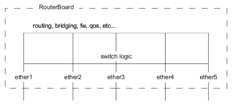
A packet that is received by one of the ports always passes through the switch logic first. Switch logic decides which ports the packet should be going to (most commonly this decision is made based on the destination MAC address of a packet, but there might be other criteria that might be involved based on the packet and the configuration). In most cases the packet will not be visible to RouterOS (only statistics will show that a packet has passed through). This is because the packet was already processed by the switch chip and never reached the CPU.
Though it is possible in certain situations to allow a packet to be processed by the CPU, this is usually called packet forwarding to the switch CPU port (or the bridge interface in bridge VLAN filtering scenario). This allows the CPU to process the packet and lets the CPU forward the packet. Passing the packet to the CPU port will give you the opportunity to route packets to different networks, perform traffic control and other software-related packet processing actions. To allow a packet to be processed by the CPU, you need to make certain configuration changes depending on your needs and on the device you are using (most commonly passing packets to the CPU is required for VLAN filtering setups). Check the manual page for your specific device:
Certain bridge and Ethernet port properties are directly related to switch chip settings. Changing such properties can trigger a switch chip reset, temporarily disabling all Ethernet ports that are on the switch chip for the settings to take effect. This must be taken into account whenever changing properties in production environments. Such properties include DHCP Snooping, IGMP Snooping, VLAN filtering, L2MTU, Flow Control, and others. The exact settings that can trigger a switch chip reset depend on the device's model.
The CRS1xx/2xx series switches support multiple hardware offloaded bridges per switch chip. All other devices support only one hardware offloaded bridge per switch chip. Use the hw=yes/no parameter to select which bridge will use hardware offloading.
Example
The following example demonstrates how to configure port switching using a bridge with hardware offloading enabled. This configuration creates a bridge interface and adds multiple Ethernet ports as bridge ports with hardware offloading enabled.
/interface/bridge
add name=bridge1
/interface/bridge/port
add bridge=bridge1 interface=ether2 hw=yes
add bridge=bridge1 interface=ether3 hw=yes
add bridge=bridge1 interface=ether4 hw=yes
add bridge=bridge1 interface=ether5 hw=yes
Verify that hardware offloading is active by checking the H flag in the bridge port table:
[admin@MikroTik] /interface/bridge/port/print
Flags: X - disabled, I - inactive, D - dynamic, H - hw-offload
 #     INTERFACE       BRIDGE       HW  PVID PRIORITY  PATH-COST INTERNAL-PATH-COST    HORIZON
 0   H ether2          bridge1      yes    1     0x80         10                 10       none
 1   H ether3          bridge1      yes    1     0x80         10                 10       none
 2   H ether4          bridge1      yes    1     0x80         10                 10       none
 3   H ether5          bridge1      yes    1     0x80         10                 10       none
Port switching in RouterOS v6.41 and newer is done using the bridge configuration. Prior to RouterOS v6.41, port switching was done using the master-port property.
Bridge VLAN Filtering
Bridge VLAN Filtering enables VLAN-aware Layer 2 forwarding and allows VLAN tag modification within the bridge. This feature makes the bridge operate more like a traditional Ethernet switch and helps resolve Spanning Tree compatibility issues that can occur when VLAN interfaces are bridged. Configuring Bridge VLAN Filtering is highly recommended to comply with STP (IEEE 802.1D) and RSTP (IEEE 802.1W) standards, and it is mandatory to enable MSTP (IEEE 802.1s) support in RouterOS.
The primary VLAN setting is vlan-filtering, which globally controls VLAN awareness and VLAN tag processing for the bridge. When vlan-filtering is set to no, the bridge ignores VLAN tags, operates in shared-VLAN-learning (SVL) mode, and cannot modify VLAN tags of packets. Enabling vlan-filtering activates all bridge VLAN-related functionality and switches to independent-VLAN-learning (IVL) mode. In addition to joining ports for Layer 2 forwarding, the bridge itself functions as an interface and therefore has a Port VLAN ID (pvid).
Currently, MikroTik devices with Marvell Prestera switch and RTL8367, 88E6393X, 88E6191X, 88E6190, MT7621, MT7531, and EN7523 switch chips (since RouterOS v7) can use bridge VLAN filtering and hardware offloading simultaneously. Other devices cannot utilize the benefits of a built-in switch chip when bridge VLAN filtering is enabled. These devices should be configured according to the method described in the Basic VLAN switching guide. Using an improper configuration method can cause throughput issues in your network.
Bridge VLAN Table
The Bridge VLAN table defines per-VLAN port membership and specifies the VLAN tag action for egress traffic. Ports configured as tagged transmit frames with their corresponding VLAN ID, while ports configured as untagged remove the VLAN tag before transmitting frames. Bridge ports with frame-types set to admit-all or admit-only-untagged-and-priority-tagged are automatically added as untagged ports for their configured PVID.
Sub-menu: /interface/bridge/vlan
| Property | Description |
|---|---|
| bridge (name; Default: none) | The bridge interface to which this VLAN entry applies. |
| disabled (yes | no; Default: no) |
| tagged (interface; Default: none) | Interfaces or interface list that transmit frames with a VLAN tag. This setting accepts comma-separated values, for example tagged=ether1,ether2. |
| untagged (interface; Default: none) | Interfaces or interface list that transmit frames without a VLAN tag. This setting accepts comma-separated values, for example untagged=ether3,ether4. |
| vlan-ids (integer 1..4094; Default: 1) | The VLAN ID or list of VLAN IDs for this port configuration. This setting accepts VLAN ID ranges as well as comma-separated values, for example vlan-ids=100-115,120,122,128-130. |
The vlan-ids parameter can specify a set or range of VLANs, but this should only be used for tagged ports configurations. When multiple VLANs are specified for access ports configurations, tagged packets may be sent as untagged packets through the wrong access port, regardless of the PVID value.
Ensure all required interfaces are added to the bridge VLAN table when using bridge VLAN filtering.
For routing functions to work properly on the same device through ports using bridge VLAN filtering, you must allow access to the bridge interface (this includes the switch-cpu port when hardware-offloaded VLAN filtering is used). This can be done manually by adding the bridge interface itself to the VLAN table as a tagged port. Since RouterOS v7.16, this is done automatically when adding a VLAN interface to a bridge with VLAN filtering enabled (a dynamic entry with the comment "added by vlan on bridge" appears under the /interface/bridge/vlan menu). Additional examples can be found in the inter-VLAN routing and management access sections.
Since RouterOS 7.20, a dynamic tagged entry named "added by switch-cpu" is added when the same VLAN ID spans multiple switch chips or is used on both hardware and software ports.
When allowing access to the CPU, you are permitting access from a specific port to the router/switch itself. This is not always desirable. Ensure you implement proper firewall filter rules to secure your device when CPU access is allowed from a specific VLAN ID and port. Use firewall filter rules to allow access only to required services.
Improperly configured bridge VLAN filtering can cause security issues. Ensure you fully understand how the Bridge VLAN table operates before deploying your device in a production environment.
Bridge Port Settings
Each bridge port has multiple VLAN-related settings that control untagged VLAN membership, VLAN tagging and untagging behavior, and packet filtering based on VLAN tag presence.
Sub-menu: /interface/bridge/port
| Property | Description |
|---|---|
| frame-types (admit-all | admit-only-untagged-and-priority-tagged |
| ingress-filtering (yes | no; Default: yes) |
| pvid (integer: 1..4094; Default: 1) | Port VLAN ID (pvid) specifies which VLAN the untagged ingress traffic is assigned to. This property only has an effect when vlan-filtering is set to yes. |
| tag-stacking (yes | no; Default: no) |
Bridge host table
The Bridge host table displays MAC addresses that have been learned on a bridge interface. When vlan-filtering is enabled, the table also shows the VLAN ID associated with each learned MAC address, enabling independent VLAN learning (IVL) mode.
[admin@MikroTik] > /interface/bridge/host/print where !local
Flags: X - disabled, I - invalid, D - dynamic, L - local, E - external
 #       MAC-ADDRESS        VID ON-INTERFACE       BRIDGE
0   D   CC:2D:E0:E4:B3:AA  300 ether3             bridge1
1   D   CC:2D:E0:E4:B3:AB  400 ether4             bridge1
VLAN Example: Trunk and Access Ports
This section demonstrates how to configure a basic VLAN setup with one trunk port and multiple access ports. The trunk port (ether2) carries tagged VLAN traffic between switches or to a router, while access ports (ether6, ether7, ether8) connect to end devices and use untagged VLAN traffic.
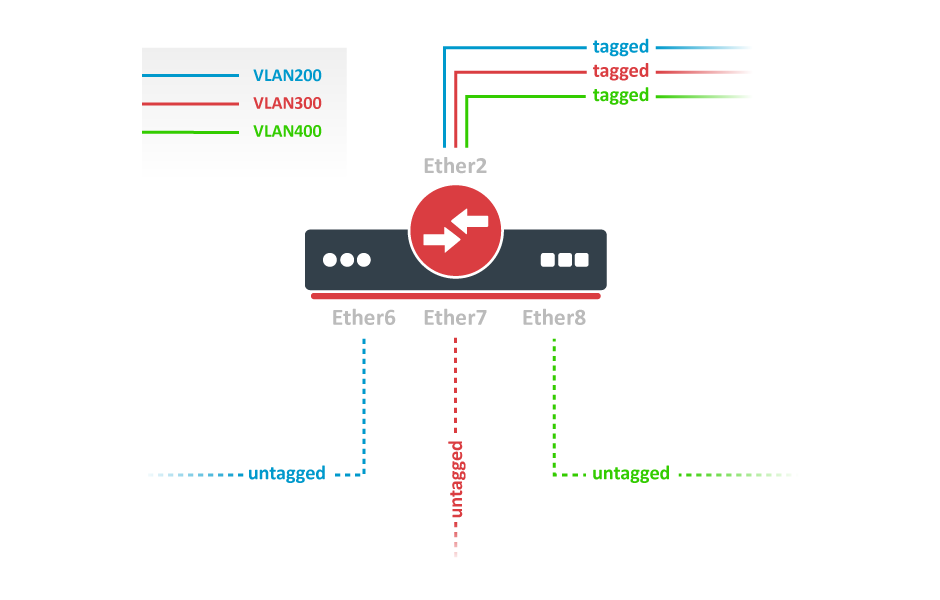
Step 1: Create the Bridge Interface
Create a bridge interface with vlan-filtering disabled. This is important because enabling VLAN filtering immediately restricts traffic, which could lock you out of the device before the configuration is complete. For detailed information on managing access to the device during VLAN configuration, refer to the Management access configuration section.
/interface/bridge
add name=bridge1 vlan-filtering=no
Step 2: Add Bridge Ports and Configure PVID
Add the physical interfaces to the bridge and configure the Port VLAN ID (pvid) for access ports. The pvid determines which VLAN untagged traffic is assigned to when entering the bridge. The frame-types setting controls what kind of traffic each port accepts: tagged only, untagged only, or both.
/interface/bridge/port
add bridge=bridge1 interface=ether2 frame-types=admit-only--tagged
add bridge=bridge1 interface=ether6 pvid=200 frame-types=admit-only-untagged-and-priority-tagged
add bridge=bridge1 interface=ether7 pvid=300 frame-types=admit-only-untagged-and-priority-tagged
add bridge=bridge1 interface=ether8 pvid=400 frame-types=admit-only-untagged-and-priority-tagged
Step 3: Create Bridge VLAN Table Entries
Create the bridge VLAN table entries. The trunk port (ether2) must be configured as a tagged member, meaning it will send and receive frames with VLAN tags. Access ports are automatically added as untagged members based on their pvid setting, so you only need to specify the tagged port in each VLAN entry.
/interface/bridge/vlan
add bridge=bridge1 tagged=ether2 vlan-ids=200
add bridge=bridge1 tagged=ether2 vlan-ids=300
add bridge=bridge1 tagged=ether2 vlan-ids=400
Step 4: Enable VLAN Filtering
Once all VLAN settings are configured, enable VLAN filtering on the bridge to activate the VLAN functionality.
/interface/bridge/set bridge1 vlan-filtering=yes
Step 5: (Optional) Reject Untagged Traffic
As an optional security measure, you can set the bridge to reject untagged traffic by changing the frame-type. This prevents the default VLAN 1 (pvid=1) from being used and ensures only properly tagged traffic is accepted.
/interface/bridge/set bridge1 frame-types=admit-only--tagged
VLAN Example - Trunk and Hybrid Ports
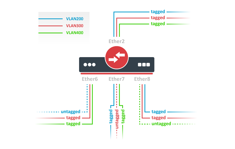
Create a bridge with disabled vlan-filtering to avoid losing access to the router before VLANs are completely configured. If you need management access to the bridge, see the Management access configuration section.
/interface/bridge
add name=bridge1 vlan-filtering=no
Add bridge ports and specify pvid on hybrid VLAN ports to assign untagged traffic to the intended VLAN. Use the frame-types setting to accept only tagged packets on ether2.
/interface/bridge/port
add bridge=bridge1 interface=ether2 frame-types=admit-only--tagged
add bridge=bridge1 interface=ether6 pvid=200
add bridge=bridge1 interface=ether7 pvid=300
add bridge=bridge1 interface=ether8 pvid=400
Add Bridge VLAN entries and specify tagged ports in them. In this example, egress VLAN tagging is done on ether6, ether7, ether8 ports too, making them into hybrid ports. Bridge ports with frame-types set to admit-all will be automatically added as untagged ports for the pvid VLAN.
/interface/bridge/vlan
add bridge=bridge1 tagged=ether2,ether7,ether8 vlan-ids=200
add bridge=bridge1 tagged=ether2,ether6,ether8 vlan-ids=300
add bridge=bridge1 tagged=ether2,ether6,ether7 vlan-ids=400
In the end, when VLAN configuration is complete, enable Bridge VLAN Filtering.
/interface/bridge/set bridge1 vlan-filtering=yes
An Optional step is to set frame-types=admit-only-vlan-tagged on the bridge interface in order to disable the default untagged VLAN 1 (pvid=1).
/interface/bridge/set bridge1 frame-types=admit-only--tagged
You don't have to add access ports as untagged ports, because they will be added dynamically as untagged ports with the VLAN ID that is specified in pvid, you can specify just the trunk port as a tagged port. All ports that have the same pvid set will be added as untagged ports in a single entry. You must take into account that the bridge itself is a port and it also has a pvid value, this means that the bridge port also will be added as an untagged port for the ports that have the same pvid. You can circumvent this behavior by either setting different pvid on all ports (even the trunk port and bridge itself), or using frame-type set to accept-only-vlan-tagged.
VLAN Example - InterVLAN Routing by Bridge
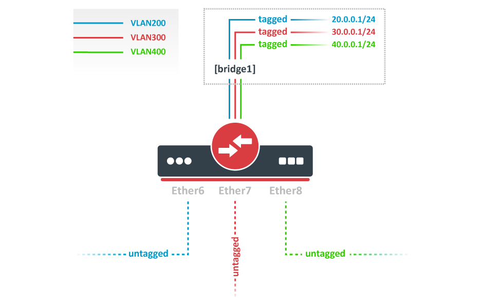
Create a bridge with disabled vlan-filtering to avoid losing access to the router before VLANs are completely configured. If you need management access to the bridge, see the Management access configuration section.
/interface/bridge
add name=bridge1 vlan-filtering=no
Add bridge ports and specify pvid for VLAN access ports to assign their untagged traffic to the intended VLAN. Use the frame-types setting to accept only untagged packets.
/interface/bridge/port
add bridge=bridge1 interface=ether6 pvid=200 frame-types=admit-only-untagged-and-priority-tagged
add bridge=bridge1 interface=ether7 pvid=300 frame-types=admit-only-untagged-and-priority-tagged
add bridge=bridge1 interface=ether8 pvid=400 frame-types=admit-only-untagged-and-priority-tagged
Add Bridge VLAN entries and specify tagged ports in them. In this example bridge1 interface is the VLAN trunk that will send traffic further to do InterVLAN routing. Bridge ports with frame-types set to admit-only-untagged-and-priority-tagged will be automatically added as untagged ports for the pvid VLAN.
/interface/bridge/vlan
add bridge=bridge1 tagged=bridge1 vlan-ids=200
add bridge=bridge1 tagged=bridge1 vlan-ids=300
add bridge=bridge1 tagged=bridge1 vlan-ids=400
Configure VLAN interfaces on the bridge1 to allow handling of tagged VLAN traffic at the routing level and set IP addresses to ensure routing between VLANs as planned.
/interface/vlan
add interface=bridge1 name=VLAN200 vlan-id=200
add interface=bridge1 name=VLAN300 vlan-id=300
add interface=bridge1 name=VLAN400 vlan-id=400

/ip/address
add address=20.0.0.1/24 interface=VLAN200
add address=30.0.0.1/24 interface=VLAN300
add address=40.0.0.1/24 interface=VLAN400
In the end, when VLAN configuration is complete, enable Bridge VLAN Filtering:
/interface/bridge/set bridge1 vlan-filtering=yes
An optional step is to set frame-types=admit-only-vlan-tagged on the bridge interface in order to disable the default untagged VLAN 1 (pvid=1).
/interface/bridge/set bridge1 frame-types=admit-only--tagged
Since RouterOS v7, it is possible to route traffic using L3 HW offloading on certain devices. See more details on L3 Hardware Offloading.
Management access configuration
There are multiple ways to set up management access on a device that uses bridge VLAN filtering. Below are some of the most popular approaches to properly enable access to a router/switch. Start by creating a bridge without VLAN filtering enabled:
/interface/bridge
add name=bridge1 vlan-filtering=no
Untagged Access Without VLAN Filtering
In cases where VLAN filtering is not enabled on the bridge and management access via untagged traffic is required, the configuration is straightforward. The only necessary step is to assign an IP address directly to the bridge interface itself. Since the bridge operates at Layer 2 without VLAN tagging, any untagged traffic entering the bridge ports will be able to communicate with the IP address assigned to the bridge interface without additional configuration.
/ip/address
add address=192.168.99.1/24 interface=bridge1
This approach provides the simplest method for accessing the router or switch for management purposes when VLAN filtering is not part of the network design.
Tagged Access Without VLAN Filtering
This method is used when you want to manage the router/switch using tagged VLAN traffic, but without enabling bridge VLAN filtering. In this scenario, a separate VLAN interface is created on top of the bridge to handle the tagged management traffic. This approach is useful when you need to access the device through a specific VLAN ID while keeping the bridge configuration simple and straightforward.
To configure tagged management access, first create a VLAN interface on the bridge with the desired VLAN ID, then assign an IP address to that VLAN interface. This allows the router to be reachable through the tagged VLAN while maintaining the bridge in its default state (without VLAN filtering enabled). The VLAN interface acts as a logical sub-interface that inherits the MAC address from the parent bridge interface.
/interface/vlan
add interface=bridge1 name=MGMT vlan-id=99
/ip/address
add address=192.168.99.1/24 interface=MGMT
This configuration creates a management VLAN (VLAN 99) on the bridge, making the device accessible at IP address 192.168.99.1 through any port that carries VLAN 99 tagged traffic.
Tagged Access with VLAN Filtering
In scenarios where VLAN filtering is enabled on the bridge and management access through tagged traffic is required, additional configuration steps are necessary. This method allows you to reach the router/switch management interface using a specific VLAN ID (VLAN 99 in this example) through tagged traffic on designated ports.
First, create a VLAN interface on top of the bridge and assign an IP address to it. This VLAN interface will handle the tagged management traffic:
/interface/vlan
add interface=bridge1 name=MGMT vlan-id=99
/ip/address
add address=192.168.99.1/24 interface=MGMT
Next, you must add the appropriate entries to the bridge VLAN table to permit tagged traffic on the ports where management access will be initiated. For instance, if you need to access the device from ports ether3, ether4, and sfp-sfpplus1 using VLAN 99 tagged traffic, include the bridge1 interface itself in the tagged port list (the bridge interface must be tagged to allow the VLAN interface to communicate with the switch CPU):
/interface/bridge/vlan
add bridge=bridge1 tagged=bridge1,ether3,ether4,sfp-sfpplus1 vlan-ids=99
Once the VLAN table is properly configured, you can enable VLAN filtering on the bridge:
/interface/bridge/set bridge1 vlan-filtering=yes
This configuration enables management access through tagged VLAN 99 traffic while maintaining the security benefits of VLAN filtering. The bridge interface itself is included as a tagged member to ensure proper communication between the VLAN interface and the switch CPU for routing and management purposes.
Untagged Access with VLAN Filtering
When bridge VLAN filtering is enabled and you need to access the device using untagged traffic, you must ensure that the management VLAN interface uses the same VLAN ID as the untagged port VLAN ID (configured via the pvid parameter). This ensures that untagged traffic from access ports can properly communicate with the router's management interface.
First, create a VLAN interface on the bridge and assign an IP address to it, just as you would in the previous example. This VLAN interface will handle the management traffic:
/interface/vlan
add interface=bridge1 name=MGMT vlan-id=99
/ip/address
add address=192.168.99.1/24 interface=MGMT
For example, if you want untagged ports ether2 and ether3 to be able to communicate with the VLAN 99 management interface, these ports must be configured with a pvid value that matches the management VLAN ID. Additionally, you need to add the bridge interface itself as a tagged port member in the VLAN table, which allows the router to process the tagged management traffic. You can also add additional tagged ports if needed for your specific network topology (see the previous examples for more details on tagged port configuration):
/interface/bridge/port
set [find interface=ether2] pvid=99
set [find interface=ether3] pvid=99
/interface/bridge/vlan
add bridge=bridge1 tagged=bridge1 untagged=ether2,ether3 vlan-ids=99
Once you have completed the VLAN table configuration, you can enable VLAN filtering on the bridge. This will activate all VLAN-related functionality and begin filtering traffic based on your VLAN settings:
/interface/bridge/set bridge1 vlan-filtering=yes
Changing untagged VLAN for the bridge interface
In case VLAN filtering is used, it is possible to change the untagged VLAN ID for the bridge interface using the pvid setting. Note that creating routable VLAN interfaces and allowing tagged traffic on the bridge is a more flexible and generally recommended option.
First, create an IP address on the bridge interface.
/ip/address
add address=192.168.99.1/24 interface=bridge1
For example, untagged bridge1 traffic should be able to communicate with untagged ether2 and ether3 ports and tagged sfp-sfpplus1 port in VLAN 99. In order to achieve this, bridge1, ether2, ether3 should be configured with the same pvid and sfp-sfpplus1 should be added as a tagged member.
/interface/bridge
set [find name=bridge1] pvid=99
/interface/bridge/port
set [find interface=ether2] pvid=99
set [find interface=ether3] pvid=99
/interface/bridge/vlan
add bridge=bridge1 tagged=sfp-sfpplus1 untagged=bridge1,ether2,ether3 vlan-ids=99
After that you can enable VLAN filtering:
/interface/bridge/set bridge1 vlan-filtering=yes
If the connection to the router/switch through an IP address is not required, then steps for adding an IP address can be skipped since a connection to the router/switch through Layer2 protocols (e.g. MAC-telnet) will be working either way.
VLAN Tunneling (QinQ)
Since RouterOS v6.43 the RouterOS bridge is IEEE 802.1ad compliant and it is possible to filter VLAN IDs based on Service VLAN ID (0x88a8) rather than Customer VLAN ID (0x8100). The same principles can be applied as with IEEE 802.1Q VLAN filtering (the same setup examples can be used). Below is a topology for a common Provider bridge:
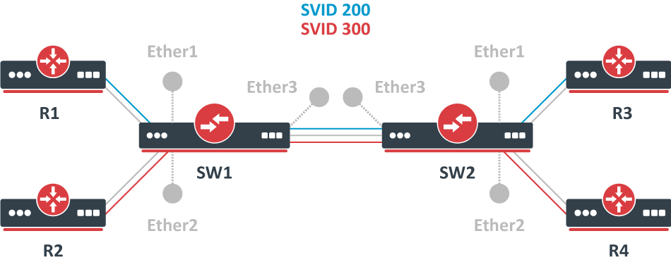
In this example, R1, R2, R3, and R4 might be sending any VLAN tagged traffic by 802.1Q (CVID), but SW1 and SW2 need to isolate traffic between routers in a way that R1 is able to communicate only with R3, and R2 is only able to communicate with R4. To do so, you can tag all ingress traffic with an SVID and only allow these VLANs on certain ports. Start by enabling the service tag 0x88a8, introduced by 802.1ad, on the bridge. Use these commands on SW1 and SW2:
/interface/bridge
add name=bridge1 vlan-filtering=no ether-type=0x88a8
In this setup, ether1 and ether2 are going to be access ports (untagged), use the pvid parameter to tag all ingress traffic on each port, use these commands on SW1 and SW2:
/interface/bridge/port
add interface=ether1 bridge=bridge1 pvid=200
add interface=ether2 bridge=bridge1 pvid=300
add interface=ether3 bridge=bridge1
Specify tagged and untagged ports in the bridge VLAN table. Use these commands on SW1 and SW2:
/interface/bridge/vlan
add bridge=bridge1 tagged=ether3 untagged=ether1 vlan-ids=200
add bridge=bridge1 tagged=ether3 untagged=ether2 vlan-ids=300
When the bridge VLAN table is configured, you can enable bridge VLAN filtering. Use these commands on SW1 and SW2:
/interface/bridge/set bridge1 vlan-filtering=yes
By enabling vlan-filtering you will be filtering out traffic destined to the CPU. Before enabling VLAN filtering you should make sure that you set up a Management port.
Note that if you are using the new EtherType/TPID 0x88a8 (service tag) and you also need a VLAN interface for your Service VLAN, you will also have to apply the use-service-tag parameter on the VLAN interface.
When ether-type=0x8100 is configured, the bridge checks the outer VLAN tag to see if it is using EtherType 0x8100. If the bridge receives a packet with an outer tag that has a different EtherType, it will mark the packet as untagged. Since RouterOS only checks the outer tag of a packet, it is not possible to filter 802.1Q packets when the 802.1ad protocol is used.
Currently, only MikroTik devices with Marvell Prestera switch are capable of hardware offloaded VLAN filtering using the Service tag, EtherType/TPID 0x88a8.
Devices with switch chip Marvell-98DX3257 (e.g. CRS354 series) do not support VLAN filtering on 1Gbps Ethernet interfaces for other VLAN types (0x88a8 and 0x9100).
Tag stacking
Since RouterOS v6.43 it is possible to forcefully add a new VLAN tag over any existing VLAN tags. This feature can be used to achieve a CVID stacking setup, where a CVID (0x8100) tag is added before an existing CVID tag. This type of setup is very similar to the Provider bridge setup. To achieve the same setup but with multiple CVID tags (CVID stacking) we can use the same topology:
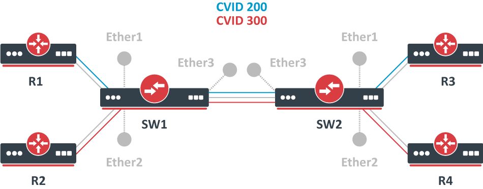
In this example R1, R2, R3, and R4 might be sending any VLAN tagged traffic, it can be 802.1ad, 802.1Q or any other type of traffic, but SW1 and SW2 need to isolate traffic between routers in a way that R1 is able to communicate only with R3, and R2 is only able to communicate with R4. To do so, you can tag all ingress traffic with a new CVID tag and only allow these VLANs on certain ports. Start by selecting the proper EtherType, use these commands on SW1 and SW2:
/interface/bridge
add name=bridge1 vlan-filtering=no ether-type=0x8100
In this setup, ether1 and ether2 will ignore any VLAN tags that are present and add a new VLAN tag. Use the pvid parameter to tag all ingress traffic on each port and allow tag-stacking on these ports. Use these commands on SW1 and SW2:
/interface/bridge/port
add interface=ether1 bridge=bridge1 pvid=200 tag-stacking=yes
add interface=ether2 bridge=bridge1 pvid=300 tag-stacking=yes
add interface=ether3 bridge=bridge1
Specify tagged and untagged ports in the bridge VLAN table. You only need to specify the VLAN ID of the outer tag. Use these commands on SW1 and SW2:
/interface/bridge/vlan
add bridge=bridge1 tagged=ether3 untagged=ether1 vlan-ids=200
add bridge=bridge1 tagged=ether3 untagged=ether2 vlan-ids=300
When the bridge VLAN table is configured, you can enable bridge VLAN filtering, which is required in order for the pvid parameter to have any effect. Use these commands on SW1 and SW2:
/interface/bridge/set bridge1 vlan-filtering=yes
By enabling vlan-filtering you will be filtering out traffic destined to the CPU; before enabling VLAN filtering you should make sure that you set up a Management port.
MVRP
Multiple VLAN Registration Protocol (MVRP) is a protocol based on Multiple Registration Protocol (MRP) which allows registering attributes (VLAN IDs in the case of MVRP) with other members of a Bridged LAN.
An MRP application can make or withdraw declarations of attributes which result in registration or leaving of those attributes with other MRP participants.
Here's how it works.
MRP consists of two parts:
- Applicant - responsible for sending declarations (or leaves). Its behavior can be configured on a per-port basis using the setting called
mvrp-applicant-state, and per-VLAN using themvrp-forbiddensetting. - Registrar - responsible for registering incoming declarations. Its configuration can be set per-port using the
mvrp-registrar-statesetting, and per-VLAN using themvrp-forbiddensetting.
Registration Propagation: Incoming registration on a bridge port dynamically makes that specific port a tagged VLAN member. Additionally, the attributes associated with this registration are spread to all active (forwarding) bridge ports as a declaration.
Declaration Operation: In case of MVRP, the configured VLANs get declared on each port, but they will only get configured as members of those VLANs when a declaration is received from the LAN (Registrar will register the VLAN). From the perspective of an end-station, a single declaration will be registered on each upstream port across the entire LAN. When another end-station declares the same attribute, a path of registrations will be made between the two (or more) end stations, see the picture below.
MVRP helps to dynamically propagate VLAN information throughout the bridged network and configure VLANs only on the needed ports. This makes the network efficient by avoiding unnecessary traffic flooding.
As noted before, MVRP is only active on ports that are forwarding. In the case of MSTP, declarations and registrations are made only if the port is forwarding in the MSTI in which the VLAN is mapped.
The point-to-point ports speed up the process of registration (or leaving). Manually configuring point-to-point=yes can be advantageous for non-Ethernet interfaces.
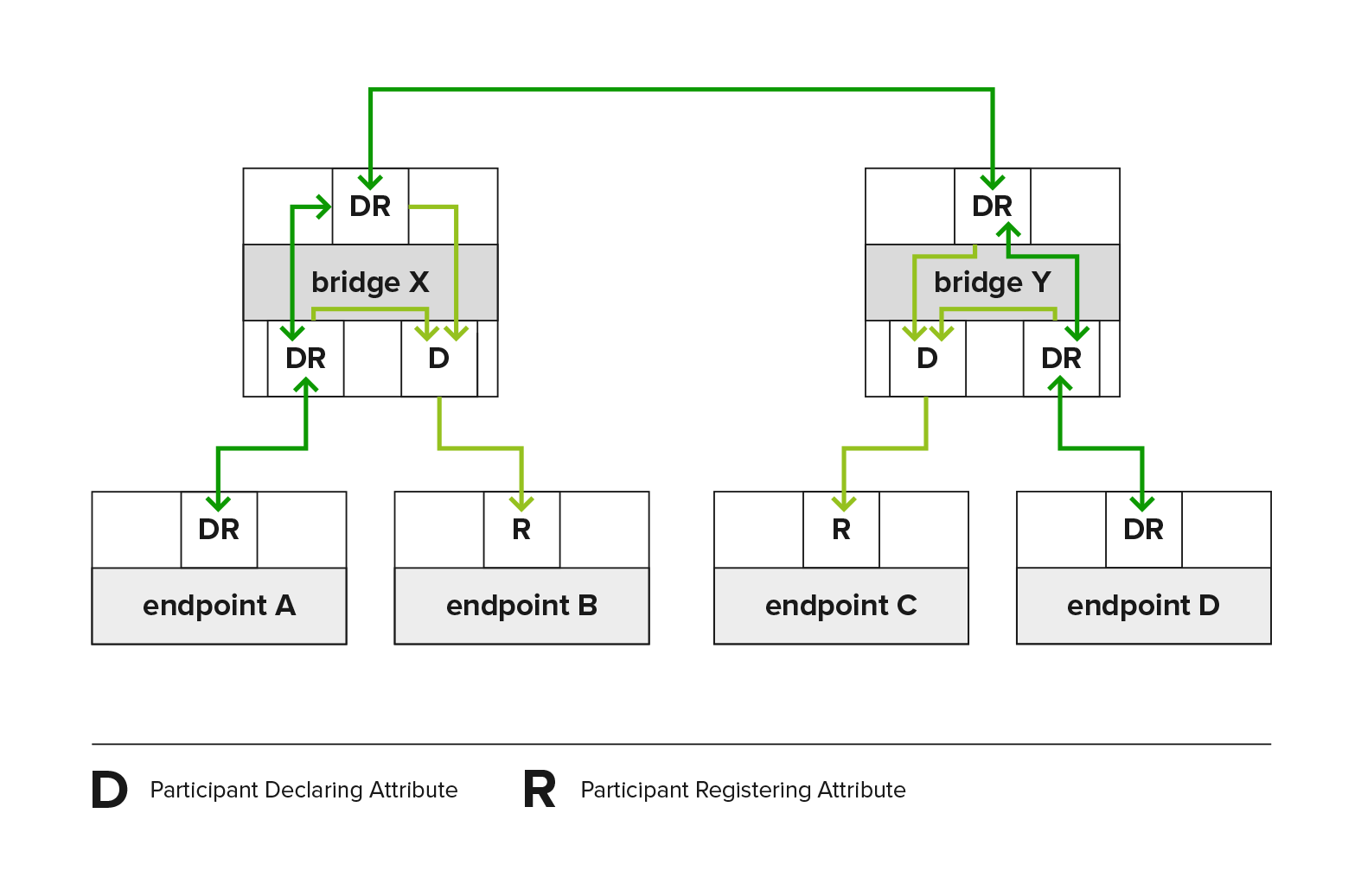
Property Reference
Sub-menu: /interface/bridge
| Property | Description |
|---|---|
| mvrp (yes | no; Default: no) | Enables MVRP for bridge. It ensures that the MAC address 01:80:C2:00:00:21 is trapped and not forwarded. The vlan-filtering must be enabled. |
Sub-menu: /interface/bridge/port
The port menu enables control over the applicant and registrar settings on a per-port basis.
| Property | Description |
|---|---|
| mvrp-applicant-state (non-participant | normal-participant; Default: normal-participant) | MVRP applicant options:
|
| mvrp-registrar-state (fixed | normal; Default: normal) | MVRP registrar options:
|
To monitor the currently declared and registered VLAN IDs, use the monitor command.
[admin@MikroTik] > /interface/bridge/port/monitor [find interface=sfp-sfpplus1]
: sfp-sfpplus1
status: in-
-number: 1
role: designated-
edge-: no
edge--discovery: yes
point-to-point-: yes
external-fdb: no
sending-rstp: yes
learning: yes
forwarding: yes
actual-path-cost: 2000
hw-offload-: switch1
declared--ids: 1,10,20-21
registered--ids: 1,10,20,30-33
Sub-menu: /interface/bridge/vlan
All ports that are members of static VLANs or dynamic untagged VLANs created by the port pvid setting are treated as "fixed." This means the registrar disregards all MRP messages and remains registered (IN) for those VLANs.
When a VLAN is neither manually configured nor created by the port pvid setting, incoming registrations on a bridge port can dynamically designate that specific port as a tagged VLAN member. The mvrp-forbidden feature allows creating a list of ports that are restricted from registering for a specific VLAN ID.
VLANs that are static or dynamic will be declared by the applicants unless this functionality is disabled by the port's mvrp-applicant-state, or by the VLAN's mvrp-forbidden setting.
| Property | Description |
|---|---|
| mvrp-forbidden (interfaces; Default: ) | Ports that ignore all MRP messages and remain Not Registered (MT), as well as disable applicant from declaring specific VLAN ID. |
Sub-menu: /interface/bridge/vlan/mvrp
The MVRP attributes menu can be used to see internal MVRP attribute states, as specified in the IEEE 802.1Q-2011.
| Property | Description |
|---|---|
| applicant-state | The Applicant state machine that declares attributes. Its state can be VO, VP, VN, AN, AA, QA, LA, AO, QO, AP, QP, or LO. Each state consists of two letters. The first letter indicates the state:
|
| registrar-state | The Registrar state machine that records the registration state of attributes declared by other participants. Its state can be IN, LV, or MT:
|
[admin@Mikrotik] /interface/bridge/vlan/mvrp/print where vlan-id=10
Columns: BRIDGE, PORT, VLAN-ID, REGISTRAR-STATE, APPLICANT-STATE, LAST-EVENT
 #  BRIDGE    PORT           VLAN-ID  REGISTRAR-STATE  APPLICANT-STATE  LAST-EVENT
 1  bridge67  sfp-sfpplus1        10  IN               Quiet Active     JoinIn
 9  bridge67  sfp-sfpplus5        10  MT               Quiet Active     JoinEmpty
17  bridge67  sfp-sfpplus9        10  MT               Quiet Active     JoinEmpty
25  bridge67  sfp-sfpplus13       10  IN               Quiet Active     JoinIn
Fast Forward
Fast Forward allows forwarding packets faster under special conditions. When Fast Forward is enabled, then the bridge can process packets even faster since it can skip multiple bridge-related checks, including MAC learning. Below you can find a list of conditions that MUST be met in order for Fast Forward to be active:
- Bridge has
fast-forwardset toyes. - Bridge has only 2 running ports.
- Both bridge ports support Fast Path, Fast Path is active on ports and globally on the bridge.
- Bridge Hardware Offloading is disabled.
- Bridge VLAN Filtering is disabled.
- Bridge DHCP snooping is disabled.
unknown-multicast-floodis set toyes.unknown-unicast-floodis set toyes.broadcast-floodis set toyes.- MAC address for the bridge matches a MAC address from one of the bridge slave ports.
horizonfor both ports is set tonone.
Fast Forward disables MAC learning; this is by design to achieve faster packet forwarding. MAC learning prevents traffic from flooding multiple interfaces, but MAC learning is not needed when a packet can only be sent out through just one interface.
Fast Forward is disabled when hardware offloading is enabled. Hardware offloading can achieve full wire-speed performance when it is active since it will use the built-in switch chip (if such exists on your device). Fast forward uses the CPU to forward packets. When comparing throughput results, you would get such results: Hardware offloading > Fast Forward > Fast Path > Slow Path.
It is possible to check how many packets were processed by Fast Forward:
[admin@MikroTik] /interface/bridge/settings> pr
use--: no
use---for-: no
use---for-pppoe: no
allow-fast-path: yes
-fast-path-active: yes
-fast-path-packets: 0
-fast-path-bytes: 0
-fast-forward-packets: 16423
-fast-forward-bytes: 24864422
If packets are processed by Fast Path, then Fast Forward is not active. Packet count can be used as an indicator of whether Fast Forward is active or not.
Since RouterOS 6.44 it is possible to monitor Fast Forward status, for example:
[admin@MikroTik] /interface/bridge/monitor bridge1
state: enabled
current-mac-: B8:69:F4:C9:EE:D7
root-: yes
root--id: 0x8000.B8:69:F4:C9:EE:D7
root-path-cost: 0
root-: none
-count: 2
designated--count: 2
fast-forward: yes
Disabling or enabling fast-forward will temporarily disable all bridge ports for settings to take effect. This must be taken into account whenever changing this property in production environments since it can cause all packets to be temporarily dropped.
IGMP/MLD Snooping
The bridge supports IGMP/MLD snooping. It controls multicast streams and prevents multicast flooding on unnecessary ports. Its settings are placed in the bridge menu and it works independently on every bridge interface. Software-driven implementation works on all devices with RouterOS, but MikroTik devices with Marvell Prestera switch, and 88E6393X, 88E6191X, 88E6190 switch chips also support IGMP/MLD snooping with hardware offloading. See more details on IGMP/MLD snooping manual.
DHCP Snooping and DHCP Option 82
DHCP Snooping and DHCP Option 82 are supported by bridge. The DHCP Snooping is a Layer2 security feature that prevents unauthorized DHCP servers from providing malicious information to users. In RouterOS, you can specify which bridge ports are trusted (where a known DHCP server resides and DHCP messages should be forwarded) and which are untrusted (usually used for access ports, received DHCP server messages will be dropped). The DHCP Option 82 is additional information (Agent Circuit ID and Agent Remote ID) provided by DHCP Snooping enabled devices that allows identifying the device itself and DHCP clients.
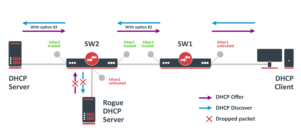
In this example, SW1 and SW2 are DHCP Snooping and Option 82-enabled devices. First, we need to create a bridge, assign interfaces and mark trusted ports. Use these commands on SW1:
/interface/bridge
add name=
/interface/bridge/port
add bridge= interface=ether1
add bridge= interface=ether2 trusted=yes
For SW2, the configuration will be similar, but we also need to mark ether1 as trusted, because this interface is going to receive DHCP messages with Option 82 already added. You need to mark all ports as trusted if they are going to receive DHCP messages with added Option 82, otherwise these messages will be dropped. Also, we add ether3 to the same bridge and leave this port untrusted, imagining there is an unauthorized (rogue) DHCP server. Use these commands on SW2:
/interface/bridge
add name=
/interface/bridge/port
add bridge= interface=ether1 trusted=yes
add bridge= interface=ether2 trusted=yes
add bridge= interface=ether3
Then we need to enable DHCP Snooping and configure Option 82. Starting from RouterOS version 7.23, it is possible to configure custom Remote ID and Circuit ID values using predefined variables (such as BRIDGEMAC, HOSTNAME, INTERFACE, VID). See the dhcp-agent-circuit-id, dhcp-agent-remote-id properties for more details. In case your DHCP server does not support DHCP Option 82 or you do not implement any Option 82-related policies, this step is not mandatory. In this configuration example, we are using these commands on SW1 and SW2:
/interface/bridge
set [find where name="bridge"] dhcp-snooping=yes dhcp-agent-circuit-id="interface: \$(INTERFACE), vlan: \$(VID)" dhcp-agent-remote-id="ip: 192.168.88.1, identity: \$(HOSTNAME), mac: \$(BRIDGEMAC)"
Now both devices will analyze what DHCP messages are received on bridge ports. The SW1 is responsible for adding and removing the DHCP Option 82. The SW2 will limit rogue DHCP servers from receiving any discovery messages and drop malicious DHCP server messages from ether3.
Currently, MikroTik devices with Marvell Prestera switch and 88E6393X, 88E6191X, 88E6190 switch chips fully support hardware offloaded DHCP Snooping and Option 82. For CRS1xx and CRS2xx series switches, it is possible to use DHCP Snooping along with VLAN switching, but then you need to make sure that DHCP packets are sent out with the correct VLAN tag using egress ACL rules. Other devices are capable of using DHCP Snooping and Option 82 features along with hardware offloading, but you must make sure that there is no VLAN-related configuration applied to the device, otherwise, DHCP Snooping and Option 82 might not work properly. See the Bridge Hardware Offloading section with supported features.
Starting from RouterOS v7.17, DHCP snooping is supported with hardware offloading on bonding interfaces.
DHCPv6 Snooping / DHCPv6 Shield
DHCPv6 Snooping is a Layer2 security feature that prevents unauthorized DHCPv6 servers from providing malicious information to users. In RouterOS, you can specify which bridge ports are trusted (where the known DHCPv6 server resides and DHCPv6 messages should be forwarded) and which are untrusted (usually used for access ports, received DHCPv6 server messages will be dropped, effectively implementing DHCPv6-Shield).
The DHCPv6 Option 18 (Interface-Id) and Option 37 (Remote-Id) are additional information provided by DHCPv6 Snooping enabled devices that allow identifying the device itself and DHCPv6 clients.
IPv6 allows a more granular approach as well as flexibility with the DHCPv6 Relay agent process. Functionally, these serve the exact same purpose as IPv4's Option 82: Option 18 acts as the Circuit ID (identifying the specific port/VLAN the client is attached to), and Option 37 acts as the Remote ID (identifying the relay agent or switch hardware itself).
- Option 18 - identifies the specific interface (port) on which the client's message was received. It ensures the server knows exactly where the request came through so it can apply the correct policy.
- Option 37 - identifies the relay agent (the switch or router) itself. It contains a unique caller ID (like the DUID—DHCP Unique Identifier). It tells the server which specific device in the network is talking to it.
RA Guard
The RA guard feature is intended for discarding IPv6 packets containing router advertisement (RA) messages arriving on bridge ports specified by the user as untrusted ones, thereby allowing one to prevent potential rogue RA message-based attacks or accidental network misconfiguration. When enabled, it is possible to set each bridge port either as trusted or untrusted (by default all the bridge ports are set as RA untrusted).
Here are the network scheme and core principle behind IPv6 RA Guard (Router Advertisement Guard).
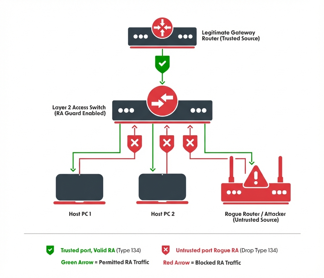
<br/>#Layer 2 Access Switch - enabling RA guard on the main bridge<br/>/interface/bridge <br/>add name=bridge<br/>/interface/bridge<br/>set [find where name="bridge"] ra-guard=yes<br/><br/>/interface/bridge/port<br/>add bridge=bridge interface=etherUplink Trusted RA=yes <br/>add bridge=bridge interface=etherX<br/>add bridge=bridge interface=etherY<br/>add bridge=bridge interface=etherZ<br/> |
The Problem: Why is this needed?
In IPv6, devices use ICMPv6 to auto-configure themselves.
Router Advertisements (Type 134): Routers broadcast these messages to tell hosts: "I am the gateway, and here is your network prefix."
The Threat: If a user accidentally connects a consumer router (like a home Wi-Fi router) or a malicious actor launches a tool (like Rogue RA) on an access port, that device will start broadcasting RAs.
The Result: Other hosts on the network will auto-configure their IPv6 addresses based on the rogue device and set the rogue device as their default gateway. This causes a Man-in-the-Middle attack or a complete denial of service.
Here is the network scheme and the core principle behind IPv6 RA Guard (Router Advertisement Guard).
The Core Principle: "Trust vs. Untrust"
The fundamental principle of IPv6 RA Guard is logically identical to DHCP Snooping in IPv4. It creates a security boundary within the Layer 2 switch infrastructure by categorizing switch ports into two roles:
- Trusted Ports: Ports connected to legitimate, authorized IPv6 routers. These ports are allowed to send Router Advertisement (RA) packets.
- Untrusted Ports: Ports connected to end-user hosts. These ports are blocked from sending RA packets.
Packet parsing process
For ports not configured as RA Trusted, the RA Guard parser traverses the extension header chain until it encounters a non-extension header. The parsing process and subsequent actions are governed by the following rules:
Transport Layer Termination: If the parser encounters a valid transport layer header—such as TCP, UDP, ESP, RSVP, or an encapsulated IPv4/IPv6 header—parsing terminates and the packet is forwarded (subject to standard bridge checks).
- Drop Conditions - The packet is discarded if:
- It fails to contain a transport layer header.
- The final extension header in the chain does not specify NO_NEXT_HEADER (59) in its "Next Header" field.
- If the ICMP message type is found to be 134, the packet is dropped.
- Fragmentation Handling: These parsing rules apply exclusively to the first fragment of fragmented IPv6 packets. Subsequent fragments are forwarded regardless of their content, as they do not contain the protocol headers necessary for RA identification.
Bridge Firewall
The bridge firewall implements packet filtering and thereby provides security functions that are used to manage data flow to, from, and through the bridge.
Packet flow diagram shows how packets are processed through the router. It is possible to force bridge traffic to go through /ip/firewall/filter rules (see the bridge settings).
There are two bridge firewall tables:
- filter - bridge firewall with three predefined chains:
- input - filters packets, where the destination is the bridge (including those packets that will be routed, as they are destined to the bridge MAC address anyway).
- output - filters packets, which come from the bridge (including those packets that have been routed normally).
- forward - filters packets, which are to be bridged (note: this chain is not applied to the packets that should be routed through the router, just to those that are traversing between the ports of the same bridge).
- nat - bridge network address translation provides ways for changing source/destination MAC addresses of the packets traversing a bridge. Has two built-in chains:
- srcnat - used for "hiding" a host or a network behind a different MAC address. This chain is applied to the packets leaving the router through a bridged interface.
- dstnat - used for redirecting some packets to other destinations.
You can put packet marks in the bridge firewall (filter and NAT), which are the same as the packet marks in the IP firewall configured by '/ip/firewall/mangle'. In this way, packet marks put by the bridge firewall can be used in the 'IP firewall', and vice versa.
General bridge firewall properties are described in this section. Some parameters that differ between nat and filter rules are described in further sections.
Sub-menu: /interface/bridge/filter, /interface/bridge/nat
| Property | Description |
|---|---|
| 802.3-sap (integer; Default: ) | DSAP (Destination Service Access Point) and SSAP (Source Service Access Point) are 2 one-byte fields, which identify the network protocol entities which use the link-layer service. These bytes are always equal. Two hexadecimal digits may be specified here to match an SAP byte. |
| 802.3-type (integer; Default: ) | Ethernet protocol type, placed after the IEEE 802.2 frame header. Works only if 802.3-sap is 0xAA (SNAP - Sub-Network Attachment Point header). For example, AppleTalk can be indicated by the SAP code of 0xAA followed by a SNAP type code of 0x809B. |
| action (accept | drop | jump | log | mark-packet | passthrough | return | set-priority; Default: ) | Action to take if the packet is matched by the rule:
|
| arp-dst-address (IP address; Default: ) | ARP destination IP address. |
| arp-dst-mac-address (MAC address; Default: ) | ARP destination MAC address. |
| arp-gratuitous (yes | no; Default: ) | Matches ARP gratuitous packets. |
| arp-hardware-type (integer; Default: 1) | ARP hardware type. This is normally Ethernet (Type 1). |
| arp-opcode (arp-nak | drarp-error | drarp-reply | drarp-request | inarp-reply | inarp-request | reply | reply-reverse | request | request-reverse; Default: ) | ARP opcode (packet type)
|
| arp-packet-type (integer 0..65535 | hex 0x0000-0xffff; Default: ) | ARP Packet Type. |
| arp-src-address (IP address; Default: ) | ARP source IP address. |
| arp-src-mac-address (MAC addres; Default: ) | ARP source MAC address. |
| chain (text; Default: ) | Bridge firewall chain, which the filter is functioning in (either a built-in one, or a user-defined one). |
| dst-address (IP address; Default: ) | Destination IP address (only if MAC protocol is set to IP). |
| dst-address6 (IPv6 address; Default: ) | Destination IPv6 address (only if MAC protocol is set to IPv6). |
| dst-mac-address (MAC address; Default: ) | Destination MAC address. |
| dst-port (integer 0..65535; Default: ) | Destination port number or range (only for TCP or UDP protocols). |
| in-bridge (name; Default: ) | Bridge interface through which the packet is coming in. |
| in-bridge-list (name; Default: ) | Set of bridge interfaces defined in interface list. Works the same as in-bridge. |
| in-interface (name; Default: ) | Physical interface (i.e., bridge port) through which the packet is coming in. |
| in-interface-list (name; Default: ) | Set of interfaces defined in interface list. Works the same as in-interface. |
| ingress-priority (integer 0..63; Default: ) | Matches the priority of an ingress packet. Priority may be derived from VLAN, WMM, DSCP or MPLS EXP bit. read more |
| ip-protocol (dccp | ddp | egp | encap | etherip | ggp | gre | hmp | icmp | icmpv6 | idpr-cmtp | igmp | ipencap | ipip | ipsec-ah | ipsec-esp | ipv6 | ipv6-frag | ipv6-nonxt | ipv6-opts | ipv6-route | iso-tp4 | l2tp | ospf | pim | pup | rdp | rspf | rsvp | sctp | st | tcp | udp | udp-lite | vmtp | vrrp | xns-idp | xtp; Default: ) | IP protocol (only if MAC protocol is set to IPv4)
|
| jump-target (name; Default: ) | If action=jump specified, then specifies the user-defined firewall chain to process the packet. |
| limit (integer/time,integer; Default: ) | Matches packets up to a limited rate. A rule using this matcher will match until this limit is reached.
|
| log(*yes | no; Default:*no) | Add a message to the system log containing the following data: in-interface, out-interface, src-mac, dst-mac, eth-protocol, ip-protocol, src-ip:port->dst-ip:port, and length of the packet. |
| log-prefix (text; Default: ) | Defines the prefix to be printed before the logging information. |
| mac-protocol (802.2 | arp | capsman | dot1x | homeplug-av | ip | ipv6 | ipx | lacp | length | lldp | loop-protect | macsec | mpls-multicast | mpls-unicast | mvrp | packing-compr | packing-simple | pppoe | pppoe-discovery | rarp | romon | service-vlan | vlan | integer 0..65535 | hex 0x0000-0xffff; Default: ) | Ethernet payload type (MAC-level protocol). To match protocol type for VLAN encapsulated frames (0x8100 or 0x88a8), a vlan-encap property should be used.
|
| new-packet-mark (string; Default: ) | Sets a new packet-mark value. |
| new-priority (integer | from-ingress; Default: ) | Sets a new priority for a packet. This can be the VLAN, WMM or MPLS EXP priority Read more. This property can also be used to set an internal priori |
| out-bridge (name; Default: ) | Outgoing bridge interface. |
| out-bridge-list (name; Default: ) | Set of bridge interfaces defined in interface list. Works the same as out-bridge. |
| out-interface (name; Default: ) | Interface that the packet is leaving the bridge through. |
| out-interface-list (name; Default: ) | Set of interfaces defined in interface list. Works the same as out-interface. |
| packet-mark (name; Default: ) | Match packets with a certain packet mark. |
| packet-type (broadcast | host | multicast | other-host; Default: ) | MAC frame type:
|
| src-address (IP address; Default: ) | Source IP address (only if MAC protocol is set to IPv4). |
| src-address6 (IPv6 address; Default: ) | Source IPv6 address (only if MAC protocol is set to IPv6). |
| src-mac-address (MAC address; Default: ) | Source MAC address. |
| src-port (integer 0..65535; Default: ) | Source port number or range (only for TCP or UDP protocols). |
| stp-flags (topology-change | topology-change-ack; Default: ) | The BPDU (Bridge Protocol Data Unit) flags. Bridges exchange configuration messages named BPDU periodically for preventing loops
|
| stp-forward-delay (integer 0..65535; Default: ) | Forward delay timer. |
| stp-hello-time (integer 0..65535; Default: ) | STP hello packets time. |
| stp-max-age (integer 0..65535; Default: ) | Maximal STP message age. |
| stp-msg-age (integer 0..65535; Default: ) | STP message age. |
| stp-port (integer 0..65535; Default: ) | STP port identifier. |
| stp-root-address (MAC address; Default: ) | Root bridge MAC address. |
| stp-root-cost (integer 0..65535; Default: ) | Root bridge cost. |
| stp-root-priority (integer 0..65535; Default: ) | Root bridge priority. |
| stp-sender-address (MAC address; Default: ) | STP message sender MAC address. |
| stp-sender-priority (integer 0..65535; Default: ) | STP sender priority. |
| stp-type (config | tcn; Default: ) | The BPDU type:
|
| tls-host (string; Default: ) | Allows matching https traffic based on TLS SNI hostname. Accepts GLOB syntax for wildcard matching. Note that the matcher will not be able to match the hostname if the TLS handshake frame is fragmented into multiple TCP segments (packets). |
| vlan-encap (802.2 | arp | ip | ipv6 | ipx | length | mpls-multicast | mpls-unicast | pppoe | pppoe-discovery | rarp | vlan | integer 0..65535 | hex 0x0000-0xffff; Default: ) | Matches the MAC protocol type encapsulated in the VLAN frame. |
| vlan-id (integer 0..4095; Default: ) | Matches the VLAN identifier field. |
| vlan-priority (integer 0..7; Default: ) | Matches the VLAN priority (priority code point) |
Footnotes:
-
STP matchers are only valid if the destination MAC address is
01:80:C2:00:00:00/FF:FF:FF:FF:FF:FF(Bridge Group address), also STP should be enabled. -
ARP matchers are only valid if mac-protocol is
arporrarp. -
VLAN matchers are only valid for
0x8100or0x88a8ethernet protocols. -
IP or IPv6 related matchers are only valid if mac-protocol is either set to
iporipv6. -
802.3 matchers are only consulted if the actual frame is compliant with IEEE 802.2 and IEEE 802.3 standards. These matchers are ignored for other packets.
Bridge Packet Filter
This section describes specific bridge filter options.
Sub-menu: /interface/bridge/filter
| Property | Description |
|---|---|
| action (accept | drop | jump | log | mark-packet | passthrough | return | set-priority; Default: accept) | Action to take if the packet is matched by the rule:
|
Bridge NAT
This section describes specific bridge NAT options.
Sub-menu: /interface/bridge/nat
| Property | Description |
|---|---|
| action (accept | drop | jump | mark-packet | redirect | set-priority | arp-reply | dst-nat | log | passthrough | return | src-nat; Default: accept) | Action to take if the packet is matched by the rule:
|
| to-arp-reply-mac-address (MAC address; Default: ) | Source MAC address to put in the Ethernet frame and the ARP payload, when action=arp-reply is selected |
| to-dst-mac-address (MAC address; Default: ) | Destination MAC address to put in Ethernet frames, when action=dst-nat is selected |
| to-src-mac-address (MAC address; Default: ) | Source MAC address to put in Ethernet frames, when action=src-nat is selected |